
|
|
|
#181
 04-10-2015, 01:44 AM
|
||||
|
||||
|
My signal generator is a rotten old EICO 324. You can sweep it manually, but calibration is a laugh.
Those two components are small and rather buried.  Seems simpler just to replace L42 unless it is unobtanium. Phil Nelson 
|
|
#182
04-10-2015, 09:23 AM
|
||||
|
||||
|
Try sweeping the combination of L42 and the 270 pF in parallel with it.
It should be close to 3.58 MHz. You could try disconnecting the 270 pF capacitor and connecting in a standard 365 pF variable, and varying that to see if you can get oscillation.
|
|
#183
04-10-2015, 09:51 AM
|
|||
|
|||
|
Quote:
Quote:
Kinda wonder if the coil could have some shorted turns in it, considering the uber-fine gauge wire it's wound with. Here's another idea that's sort of a 'Hail Mary' gambit.. See if the osc. can be made to free-run on just the crystal. Disconnect the LC tank completely and replace it with a resistor (leaving feedback cap C209 in place). Try several values of resistor, from maybe 47 ohms thru 560 ohms or more. If it'll start and run, that would pretty well confirm the fault lies with the LC combo. Last edited by old_coot88; 04-10-2015 at 10:14 AM.
|
|
#184
04-10-2015, 10:17 AM
|
||||
|
||||
|
I simulated the circuit. The cathode tank needs to resonate
a bit below 3.58 MHz. Apparently its doing some phase shifting. It seems non critical, 2.5 to 3.2 seems to work.
|
|
#185
04-10-2015, 12:04 PM
|
||||
|
||||
|
It's difficult to sneak a soldering iron into the place where those two components connect to the tube, much less other tools. In the event that I fry or mangle L42 in the course of experiments, what's a good replacement -- something like this?
http://www.mouser.com/ProductDetail/...tRRhUO5QN1Y%3d Phil Nelson
|
| Audiokarma |
|
#186
04-10-2015, 01:40 PM
|
|||
|
|||
|
I would say go for it. The extreme disparity in DC resistance is no doubt due to its having a ferrite core vs. the original's air core (hence fewer turns of wire).
|
|
#187
04-11-2015, 02:08 AM
|
||||
|
||||
|
I disconnected C213 and L42 from the oscillator tube, and when I lifted up L42, it looked scorchy:
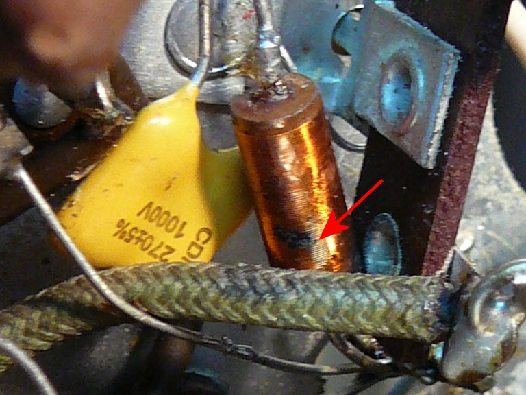 There was a layer of melted varnish sticking it to the green wire below. (I scraped that off before taking the photo.) The coil is missing varnish in the area where they touched, and some of its wires look burned black. It has continuity, measuring 2.6 ohms resistance. Not having another coil to compare, I have no idea what that figure means; if it has shorted coils, I suppose it could show continuity but have the wrong inductance. Quote:
It's possible I had things set up wrong. What I did was to connect C213 and L42 in parallel (but disconnected from the tube). Then I connected the sig gen at one end of this pair and the scope at the other end. I slowly changed the frequency of the sig gen and watched for a peak of some kind. Again, with my crude old generator, it's not possible to s-l-o-w-l-y vary the frequency around that exact point, or even hold it precisely, except at whatever frequency it flops to when you let go of the knob. Phil Nelson
|
|
#188
04-11-2015, 11:05 AM
|
|||
|
|||
 Dang. That swatch of carbonization looks like it involved a half dozen turns or more. That could sure play hobb with the 'Q' factor as well as alter the inductance. Dang. That swatch of carbonization looks like it involved a half dozen turns or more. That could sure play hobb with the 'Q' factor as well as alter the inductance. Re. the sweep test, what you'd wanta do is leave coil and cap in parallel, with the lower end grounded. Then connect both genny and scope to the top (with their cable shields grounded, of course). A parallel-resonant LC tank (which this is) exhibits highest impedance at resonance, grounding out all other frequencies. But a series-resonant tank (L and C in series) exhibits lowest impedance at resonance, making it useful as a wave trap to ground out an unwanted signal.
|
|
#189
04-11-2015, 12:17 PM
|
||||
|
||||
|
OK. I visited the local surplus store and found a couple of 12muh inductors in a bin. Later today I'll try the sweep test on old & new parts and see what transpires.
Phil Nelson
|
|
#190
04-11-2015, 12:46 PM
|
|||
|
|||
|
To get the sharpest blip, you'd probably wanta use a small coupling cap from the gen to the tank. Maybe 10 pf or so.
|
| Audiokarma |
|
#191
04-11-2015, 04:09 PM
|
||||
|
||||
|
Is this what you're talking about -- 270pf cap in parallel with the inductor, and 10pf on the end?
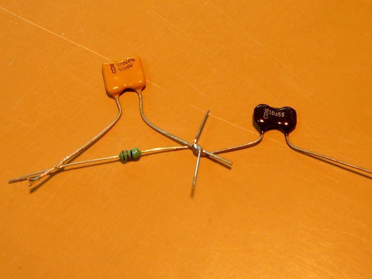 Seems to do nothing around 3.58 mc, but when I went lower, I could get a waveform showing up between about 2.3 to 2.7 mc, peaking in amplitude around 2.55 mc.  Out of curiosity, I made another little circuit using the old L42 and two more caps (10 and 270 pf). The response was basically the same.  So, either the original L42 was good after all, or I still don't have things set up correctly. (Or it could be some evil combination of antique signal generator, middle-aged scope, and antique brain  ) )Meanwhile, I installed a new inductor in place of the old L42 in the TV and reconnected things to the oscillator tube. No change or improvement. Still seeing 0 volts at pin 6 of the oscillator. Phil Nelson Last edited by Phil Nelson; 04-11-2015 at 04:16 PM.
|
|
#192
04-11-2015, 04:34 PM
|
|||
|
|||
|
some obvious stuff here, is the tube socket good (use a test socket to make sure the tube pins are connected to the circuit. Different tube used? correct tube used? just trying to cover the bases.
|
|
#193
04-11-2015, 04:42 PM
|
||||
|
||||
|
Here is a crazy thought what if there is a tin whisker or some such shorting the grid to ground forcing it to be 0V?
__________________
Tom C. Zenith: The quality stays in EVEN after the name falls off! What I want. --> http://www.videokarma.org/showpost.p...62&postcount=4
|
|
#194
04-11-2015, 04:53 PM
|
|||
|
|||
|
Is that a low capacitance scope probe? If not, it may be pulling the tank freq down too much. To minimize loading, you could add a small cap in series with the probe. Just a 'gimmick' consisting of a few inches of wire twisted together should do it.
If you need to raise the freq, try a lower value tank cap. Maybe 100 pf to start, and see which direction you have to go from there. Last edited by old_coot88; 04-11-2015 at 05:08 PM.
|
|
#195
04-11-2015, 08:54 PM
|
||||
|
||||
|
It is a plain old direct scope probe. I tried adding a 2 pf cap in series with the probe and didn't notice a significant change.
I tried substituting a 100 pf and a 82 pf cap for the 270 pf cap in the tank circuit on the workbench. 100 pf raised the peaking point somewhat, and 82 pf raised it up to roughly 3.5 mc. I substituted an 82 pf cap in the TV, and observed no change or improvement. I don't see any whiskers or solder crumbs anywhere on the socket, which I have cleaned and re-cleaned. I have tested the socket with an adapter in place, and tried running the TV with the tube in an adapter, with and without the shield. When I tested the old coil (L42) in a tank circuit on the workbench, it responded the same as a new one. Substituting a new coil for the old one in the TV gives me the same result. I guess I can't rule out a socket defect such as a hidden carbon track caused by a past shorting incident. That is a hard thing to disprove without stripping everything off the socket, at which point you may as well simply replace it. Phil Nelson
|
| Audiokarma |
 |
|
|


 Linear Mode

