Videokarma.org

Go Back   Videokarma.org TV - Video - Vintage Television & Radio Forums > Early B&W and Projection TV

We appreciate your help

in keeping this site going.
Reply
 
Thread Tools Display Modes
  #46  
Old 04-30-2016, 09:23 PM
timmy's Avatar
timmy timmy is offline
VideoKarma Member
 
Join Date: Jan 2011
Location: ferndale ny
Posts: 3,530
Quote:
Originally Posted by Eric H View Post
Bear in mind this set isn't supposed to fill the entire face of the tube, there should be a blank space on top and bottom that's covered by the mask.
If you're trying to fill the entire tube face it might just bee too much for the circuitry to handle.
Well the verticle size pot is maxed and there is to much missing on the bottom so there must be something else going on. There is so much missing that the mask won't hide it. Even trying to balance it with the verticle center there is still some missing.
Reply With Quote
  #47  
Old 05-01-2016, 11:04 AM
timmy's Avatar
timmy timmy is offline
VideoKarma Member
 
Join Date: Jan 2011
Location: ferndale ny
Posts: 3,530
Does anyone know of another way to check hv on this pilot using a regular 0-42 kv hv tester that does work maybe using resistors or a microwave resistor in some configuring way because I do think the hv is low as everything else checks out perfect. They say you cannot use a tester like I have due to high impedance. There must be a way I have nothing else except an analog meter that only goes to 1 kv and even that meter don't go to 1 kv to say that the hv is infact low because my meter should pin if more the 1000 volts.
Reply With Quote
  #48  
Old 05-01-2016, 12:08 PM
timmy's Avatar
timmy timmy is offline
VideoKarma Member
 
Join Date: Jan 2011
Location: ferndale ny
Posts: 3,530
Ok so I'm about done with this but I have to ask , anyone that has a pilot tv is the vert size maxed to one side and is the vert center almost maxed to one side and at the top and bottom where there is Alittle of the picture missing does the bottom part have what looks like the image is compressed upward because it won't go down anymore because the size pot is maxed? Because this is what I'm left with I'm sure the pots should not be maxed to try to get the screen right there is not much swing towards the bottom and the image should certainly not be pushed up when it belongs on the bottom.
Reply With Quote
  #49  
Old 05-01-2016, 12:25 PM
reichsrundfu reichsrundfu is offline
VideoKarma Member
 
Join Date: Jun 2013
Posts: 96
..... The image that you are getting right now: how bright is it and how sharp is it and how much greyscale definition is it???

I'm not that comfortable with the thought that the problem is principally related to low HV...

Now, if you have swapped out the CRT and have the same result, you know the issue is in the chassis vertical section. Two thoughts if you haven't done so already: try swapping out the tubes in the vertical section. If no change I'd Think outside the box and try changing capacities of caps in the vertical sweep. And I'd begin with mica's..... Yes I know you've checked stuff 30+ times visually, but there is something fairly basic going on and you should have confidence in and start trusting your gut. Ask me how many times I've worked my ass out of goofy, arcane weird problems in both radio and television restoration work like this. Something not visually obvious is off. Most likely a capacitor. Check each cap you replaced. I've run into plenty of perfectly good looking new caps that were bad. And as for micas--- I have little faith in originals anymore. Just sayin'... And of course take a break and have a nice drink (a good Bombay martini is my fav and never failed to appropriately clear my brain for serious thinking) and the problem will just whack you right in the face. You're very close. This is not a huge issue. Just think you're looking under the wrong slimy rock (like all of us have on occasion...)

For a "fer instance" last fall I bought a Predicta from a guy who spent forever trying to figure out a (vertical) double image issue. I put it on the bench and after verifying everything was "visually " correct determined the vertical oscillator was just running too fast. I really didn't give a rats ass why -- everything "checked out" so I just changed the resistance to the hold circuit and the problem corrected itself. After over 5 months it's running like a Swiss watch. Just go with your gut and use your experience!!! It's something easy...

George
Reply With Quote
  #50  
Old 05-01-2016, 12:39 PM
Eric H's Avatar
Eric H Eric H is offline
Administrator
 
Join Date: Jun 2002
Location: So. Calif
Posts: 11,565
I noticed you said in post #7 that Ceramic Disc caps were used, if those are the high voltage caps in the vertical circuit then that's probably your problem.

Discs will work in the horizontal but not the vertical, they will cause linearity problems.
Reply With Quote
Audiokarma
  #51  
Old 05-01-2016, 12:40 PM
timmy's Avatar
timmy timmy is offline
VideoKarma Member
 
Join Date: Jan 2011
Location: ferndale ny
Posts: 3,530
Quote:
Originally Posted by reichsrundfu View Post
..... The image that you are getting right now: how bright is it and how sharp is it and how much greyscale definition is it???

I'm not that comfortable with the thought that the problem is principally related to low HV...

Now, if you have swapped out the CRT and have the same result, you know the issue is in the chassis vertical section. Two thoughts if you haven't done so already: try swapping out the tubes in the vertical section. If no change I'd Think outside the box and try changing capacities of caps in the vertical sweep. And I'd begin with mica's..... Yes I know you've checked stuff 30+ times visually, but there is something fairly basic going on and you should have confidence in and start trusting your gut. Ask me how many times I've worked my ass out of goofy, arcane weird problems in both radio and television restoration work like this. Something not visually obvious is off. Most likely a capacitor. Check each cap you replaced. I've run into plenty of perfectly good looking new caps that were bad. And as for micas--- I have little faith in originals anymore. Just sayin'... And of course take a break and have a nice drink (a good Bombay martini is my fav and never failed to appropriately clear my brain for serious thinking) and the problem will just whack you right in the face. You're very close. This is not a huge issue. Just think you're looking under the wrong slimy rock (like all of us have on occasion...)

For a "fer instance" last fall I bought a Predicta from a guy who spent forever trying to figure out a (vertical) double image issue. I put it on the bench and after verifying everything was "visually " correct determined the vertical oscillator was just running too fast. I really didn't give a rats ass why -- everything "checked out" so I just changed the resistance to the hold circuit and the problem corrected itself. After over 5 months it's running like a Swiss watch. Just go with your gut and use your experience!!! It's something easy...

George
I thought maybe a cap but I desoldered the caps in and around the verticle and checked then for the proper nf and they were off by maybe, 1-2 numbers not enough to cause this. And yes I tried different cap values and resistor values and nothing works. The sound is perfect and the picture is sharp and clear. I did adjust the hv at the 1b3 and the variable cap and the pic is brighter but all I have is the 3kp1 green cry and they are not bright so maybe the hv is good but the verticle is not. I've seen verticle like this befor with the bottom line looking compressed. So both crts same thing. There are no Micas in this verticle only in the horiz and they are new . I subbed a .02 with a 20 pf mica no change but I think the .05 caps are the ones that are responsible for what it lacks so even thought the .05 caps check good under load they could be changing value. Could this be a sync sep problem
Reply With Quote
  #52  
Old 05-01-2016, 03:39 PM
timmy's Avatar
timmy timmy is offline
VideoKarma Member
 
Join Date: Jan 2011
Location: ferndale ny
Posts: 3,530
Quote:
Originally Posted by Eric H View Post
I noticed you said in post #7 that Ceramic Disc caps were used, if those are the high voltage caps in the vertical circuit then that's probably your problem.

Discs will work in the horizontal but not the vertical, they will cause linearity problems.
Yes it did have ceramics in the deflection but I took them out and put asc caps but that was not the problem so here is an update. I believe these 2 caps were integrator caps, 2 -.05 caps and I have a tester and they tested good so I left them then decided to take one out at a time and sub well the SAMs shows .05 caps belong there in the schematic but listed in the parts shows unless I looked at it wrong .005 so I don't know. Anyway I put .033 for one .05 and the other .47 and it fixed it perfect although I tried it the other way and didnt work then switched them back and it's done finally. The .47 went between v13 and v14 and the .33 from v13 to the 120 k below it. Here are befor and after pics.

Last edited by timmy; 04-24-2023 at 04:16 PM.
Reply With Quote
  #53  
Old 05-01-2016, 03:43 PM
timmy's Avatar
timmy timmy is offline
VideoKarma Member
 
Join Date: Jan 2011
Location: ferndale ny
Posts: 3,530
Ok here's the befor . Ok I won't let me put it up again it's on page 2 the way it was.

Last edited by timmy; 05-01-2016 at 03:50 PM.
Reply With Quote
  #54  
Old 05-01-2016, 04:37 PM
timmy's Avatar
timmy timmy is offline
VideoKarma Member
 
Join Date: Jan 2011
Location: ferndale ny
Posts: 3,530
Will a 3fp7 crt work in the pilot tv if wired to the set, anything has got to be better and brighter then the green?
Reply With Quote
  #55  
Old 05-01-2016, 05:06 PM
jr_tech's Avatar
jr_tech jr_tech is offline
VideoKarma Member
 
Join Date: Sep 2009
Posts: 4,515
P-7 is a long persistance yellow excited by a short persistance blue (like one might use in a radar display tube) It will look terrible in a tv application. Green P-1 looks much better and does not have the smeared appearance.

jr
Reply With Quote
Audiokarma
  #56  
Old 05-01-2016, 05:22 PM
jr_tech's Avatar
jr_tech jr_tech is offline
VideoKarma Member
 
Join Date: Sep 2009
Posts: 4,515
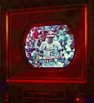
Here is a video that Bandersen shot... near the end of the video is a P-7 jug.
Although it is out of focus, you can clearly se the undesirable effect produced by the long persistance yellow of P-7 phosphor. A blue filter that does not pass yellow light could help, but IMHO, will not look vvery good.

https://m.youtube.com/watch?v=crBqt606qOg

jr
Reply With Quote
  #57  
Old 05-01-2016, 05:22 PM
timmy's Avatar
timmy timmy is offline
VideoKarma Member
 
Join Date: Jan 2011
Location: ferndale ny
Posts: 3,530
Is this tube brighter and it wouldn't be any better then the green as I thought anything other then green has got to be somewhat better.
Reply With Quote
  #58  
Old 05-02-2016, 03:20 PM
reichsrundfu reichsrundfu is offline
VideoKarma Member
 
Join Date: Jun 2013
Posts: 96
You're basically there Tim. Hold out for a P4 CRT and you should be good to go. Just adjust down your height to fill the mask!

George
Reply With Quote
  #59  
Old 05-02-2016, 04:37 PM
timmy's Avatar
timmy timmy is offline
VideoKarma Member
 
Join Date: Jan 2011
Location: ferndale ny
Posts: 3,530
I don't think I'll ever find a p4 it will be impossible. So if I tried a 3kp7 and used the 3rd anode or not will I get a picture because they say that a yellow or blue filter can be used because the green sucks its dim after all it is only 3 inch so I read to use the other anode for either fast or slow so I can't find anything that says it will work. I did see that tube with a clear picture but it was really small. If that anode was used then would I have to run a wire from the 1b3 output to the anode ? It is clear but not bright even the other crt I have is not bright but it is green .
Reply With Quote
  #60  
Old 05-02-2016, 05:20 PM
bandersen's Avatar
bandersen bandersen is offline
RCA 741PCS
 
Join Date: Mar 2009
Location: Chicago, IL
Posts: 8,103
The 3KP7 has an identical pinout as the 3KP4. No need to run any additional wires.
__________________
Here are my Vintage Radio & TV YouTube Channel and Photo Gallery
Reply With Quote
Audiokarma
Reply


Posting Rules
You may not post new threads
You may not post replies
You may not post attachments
You may not edit your posts

BB code is On
Smilies are On
[IMG] code is On
HTML code is Off

Forum Jump


All times are GMT -5. The time now is 12:55 AM.


Powered by vBulletin® Version 3.8.4
Copyright ©2000 - 2024, Jelsoft Enterprises Ltd.
©Copyright 2012 VideoKarma.org, All rights reserved.