
|
|
|
#16
 05-09-2018, 12:46 PM
|
||||
|
||||
|
I cut them apart so I could test them
 They were in parallel when they were in the set. They were in parallel when they were in the set.

|
|
#17
05-10-2018, 10:47 AM
|
||||
|
||||
|
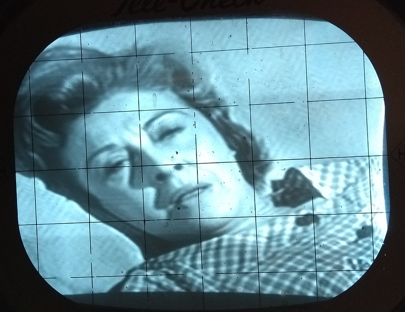
Replace a few more caps and resistors and image continues to improve.
 I hadn't realized until last night that the sound circuit in the lower left show in Sams is hand wired while mine is on a PCB. That's pretty big production run change! 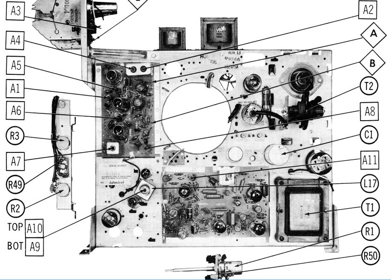 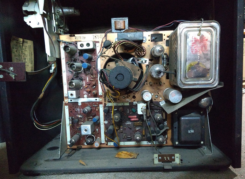
|
|
#18
05-10-2018, 12:05 PM
|
||||
|
||||
|
Thanks for being just as thorough on Admirals more typically found than your interesting old Admirals
 I have a 1952 bakelite 17" and a 1955 21" floor model that are pretty common, so this is a very encouraging thread. I have a 1952 bakelite 17" and a 1955 21" floor model that are pretty common, so this is a very encouraging thread.
__________________
"When resistors increase in value, they're worthless" -Dave G
|
|
#19
05-10-2018, 09:04 PM
|
||||
|
||||
|
It's nice to see a recognizable set being restored on VK. (We only have sets from 56 onwards in Aus) and it's a chassis I actually have personal knowledge of. Restoreable old sets in Aus are hard to find and people want the earth for them. It's really got to be a barn find to be worthwhile.
|
|
#20
05-11-2018, 10:06 AM
|
|||
|
|||
|
Quote:
The audio panel also uses an octal output tube and the yoke is hard-wired as I stated before.
|
| Audiokarma |
|
#22
05-15-2018, 10:43 AM
|
||||
|
||||
|
Well spotted. I think it makes sense that the later run would use a circuit board to speed up production.
|
|
#23
11-11-2019, 11:28 AM
|
||||
|
||||
|
I'm still puttering around with the set more than a year later. It's been fully recapped and the very few resistors that were out of spec have been replaced.
Remaining issues - out of focus image, unstable vertical hold, audio buzz and a floppy tuner assembly.
|
|
#24
11-11-2019, 11:41 AM
|
||||
|
||||
|
Now to get everyone up to speed on where I'm at.
All the wires were very sticky. I saw EM post that this is due to the plasticizer oozing out over the years. Denatured alcohol does a good cleaning it up.  As for the tuner, it's only held on by two screws and floats on rubber grommets. The tuner chassis is grounded via a braided copper strap to the main chassis. I assume they did this to minimize vibration to the mixer / oscillator tube. I tried using some reproduction grommets I had for vintage radio tuning caps but they were too soft. A quick trip the hardware store for some harder grommets and washers did the trick. 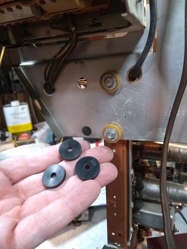 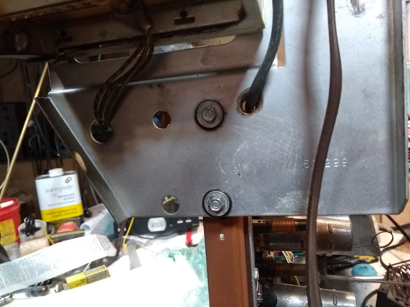 I did some voltage checks to track down the blurry image and found the HV was about 11 kV instead of 15.5 and the 440 V boost was only 315. I tried swapping 6DQ6 HO tubes, tweaking the drive control and double checked my work. Nothing helped. Voltages on the 6DQ6 are normal. Working my way back I found the plate voltage on the horizontal osciallator about 50 low. It also appears the vertical integrator has been replaced and it's resistance is measuring about twice what it should be. Got frustrated trying to work on that board so just unmounted the darn thing! I'd already clipped out a few mica caps hoping to find a leaky one but they all tested fine. 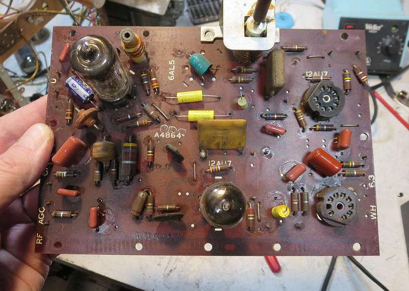 At least now I can really go to town. That will include replacing the dual selenium phase detector with schottky diodes and building a discrete vertical integrator.
|
|
#25
11-11-2019, 11:43 AM
|
||||
|
||||
|
Interesting how they removed pin 8 and cut a hole round pin 9 of the 6S4 vertical output tube.
I assume that was to prevent arc over or breakdown of the phenolic PCB 
|
| Audiokarma |
|
#26
11-11-2019, 12:17 PM
|
||||
|
||||
|
Quote:
__________________
Tom C. Zenith: The quality stays in EVEN after the name falls off! What I want. --> http://www.videokarma.org/showpost.p...62&postcount=4
|
|
#27
12-13-2019, 12:11 PM
|
||||
|
||||
|
Finally making some real progress on this set after 18 months!
The sweep board is done including rebuilding the vertical integrator couplate using C0G type ceramic caps.  After reinstalling, vertical hold was rock solid, but CRT anode and boost voltages still about 40% low. I thought maybe an impedance mismatch using the CRT substitution box was the cause. So I hooked up the set's yoke with an 8XP4 propped in place. It made no difference what so ever.  I did some more research and discovered the voltages and waveforms in the Riders service info for the horizontal circuit differed from the Sams and matched what I was measuring. I also noticed the Riders shows a 6CU6 HOT while the Sams a 6DQ6. Sure enough that's what's on the tube chart. So I dug up a couple 6CU6s and tried them. HV was even lower ! The specs are very similar though so I went back to trying some NOS 6DQ6s. Bam, finally as I was about to give up, I found a 6DQ6 that got the voltages right where they should be! I've never encountered a set so picky about tube before. Now with 15+ kV and a 520 V boost, the image more than fills the little test CRT screen and the focus is sharp. I do get some interference on the screen, but otherwise the set is working very well. Next I'll make sure all connections are tight and all shields are in place. 
|
|
#28
12-23-2019, 01:00 PM
|
||||
|
||||
|
Turns out the interference was from the OTA conversion box I used. I switched to using my Blonder Tongue home transmitting setup and no more static.
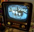
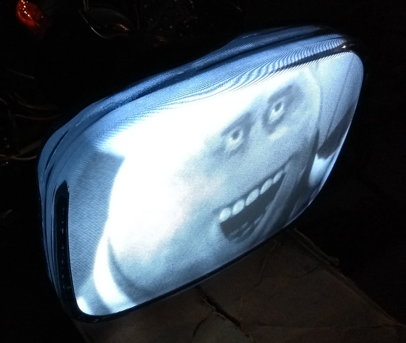 I put the the chassis in the cabinet and hooked up the full size CRT. Immediately I hear HV hiss and smelled ozone. I was able to get a raster though. Turned out the VH anode connected boot was rock hard and not able to make a good seal. I replaced it with a newer, pliable one and the hiss went away. Not the greatest image but I think that due to the distance from my transmitter and suboptimal antenna. I'll get everything installed and secure then go through the setup procedure for linearity, centering etc. I'll be glad to get this one done. 
|
|
#29
12-27-2019, 09:46 AM
|
||||
|
||||
|
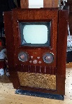
While tracking down the source of interference, I noticed that it made no difference when I moved the grounding loop away from the dag CRT coating.
I used some fine sandpaper on the wire loop and put a piece of aluminum foil between it and the dag. That seems to have fixed it  That fixed it  Also was fighting some horrible height and linearity issues. Turned out I had two resistors swapped. A 15K where a 1.8M should have been. Fixed that up and finally the height control actually does something useful now   IMG_20191227_002743390 IMG_20191227_002743390Time to button the set up and call it done!
|
 |
|
|


 Linear Mode

