
|
|
|
|
|
#1
 11-04-2017, 04:29 PM
|
||||
|
||||
|
Sinclair mtv1
Anyone know the Sinclair mtv1 tv , I just picked one up on eBay so I had a power pack and it turned right on and had sound but just a hint of a pic so I shut it and this morning took it apart to replace the ni cads and did so and now it has just a hiss like no antenna for sound and no hint of a picture. Maybe they are known for something specific I don't know. I changed caps in the IF board and made no difference. The schematic shows voltages on the IF board as well as the audio board and are close to where they should be including the 33 volts for the tuner. Any help would be great.

|
|
#2
11-04-2017, 06:24 PM
|
||||
|
||||
|
Pls elaborate on hint of pix. Also did it have normal sound like from
a source ? A normal good running TV should have nice strong clean snow & a nice waterfall with no signal. Weak snow or a blank screen points to the IF most the time. Depending on the design the 33 V may go right to the tuner or be divided down before. Also band switching can be external or internal to the tuner. Newer sets will do everything inside the TNR & have data, 5V, & clock pins........ BTW https://elektrotanya.com/sinclair_mi.../download.html 73 Zeno  LFOD !
|
|
#3
11-04-2017, 07:17 PM
|
|||
|
|||
|
Make sure that all plug connections are in right and also check for broken solder joints around the connectors, they are easy to break on that little beast. Also no see'm gunk buildup on the boards can stop them in there tracks. Had those problems with my MTV1 and MTV2. All the best, Tom.J
|
|
#4
11-04-2017, 07:20 PM
|
||||
|
||||
|
Quote:
|
|
#5
11-04-2017, 07:18 PM
|
||||
|
||||
|
Well the pic was bearly a shadow of something but really couldn't make it out. The sound was clear and it was from a source, cable with the matching transformer so it was a good signal. The screen is lit but blank and snow for sound. I traced the 33v source right to the tuning knob or whatever it's called it also has the 45v source. I changed the caps on the video-IF board but nothing helped at all. I just thought there may be a common thing with these sets. It makes no sense , sound then nothing after putting new battery's in and I also took the battery's back out to double check that I didn't hit something in there but it was all good and intact. One end of the 33v is at the IF then to an IC then out as 45v but the 33v does branch off also but there are no bad traces, checked them all.
|
| Audiokarma |
|
#6
11-04-2017, 08:28 PM
|
|||
|
|||
|
I'm talking about the stuff that will kill any hi impedance circuit, like mos or c-mos logic or analog circuits. I have seen way to many boards tossed when all they needed was a good cleaning. Showed young bucks what was needed to keep things going, but most didn't want to take the time to find out what the real trouble was. Not saying that is your problem but something to look into. All the best, Tom.J
|
|
#7
11-06-2017, 02:41 PM
|
||||
|
||||
|
Well I may have a clue what's wrong with this little set after reading an old thread from someone in London as he says that the tuner is dead because the varicaps are no good which oscillate the tuner so what does this type of varicap diode look like and does it make a difference what the voltage is which is supplied with 33 volts. I know these varicaps tune the tuner but this guy said there are no marks on these diodes only colors. The thread was short so couldn't get much more info.
|
|
#9
11-07-2017, 05:18 AM
|
||||
|
||||
|
Quote:
Can you give a closer pic of where the 2 antenna wires go on the board. For all I know at this point you could have the same problem as I have only yours didn't get to the point mine is at now. There are a lot of these sets out there with the same thing going on with them, after all they are 39 years old not like the old sets resistors and caps and tubes and they work. I checked caps and as amazing as it is all caps I checked were above MF which is good. If you give up on yours and want to sell it to me maybe I could use parts for either one and just maybe I could get one working. Last edited by timmy; 11-07-2017 at 10:52 AM.
|
|
#10
11-07-2017, 01:42 PM
|
||||
|
||||
|
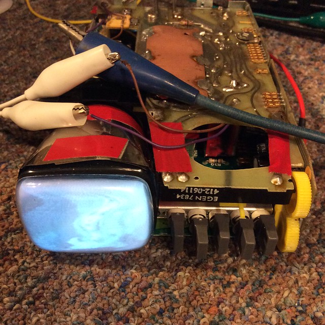
As requested... pix of antenna connection to board.
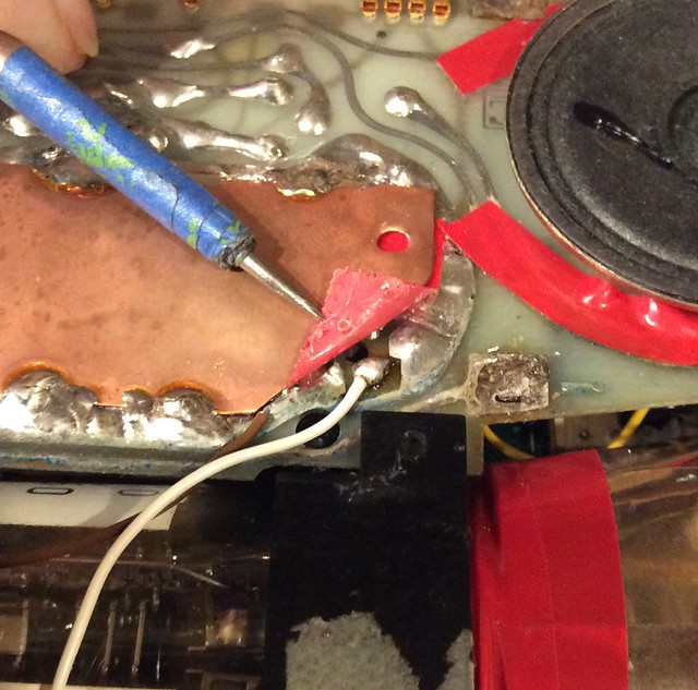 Made some progress... installed my one good speaker, resoldered the antenna connection, tuned my DTV converter box to ch 3, swapped out Video board and was rewarded with a decent pix and sound. 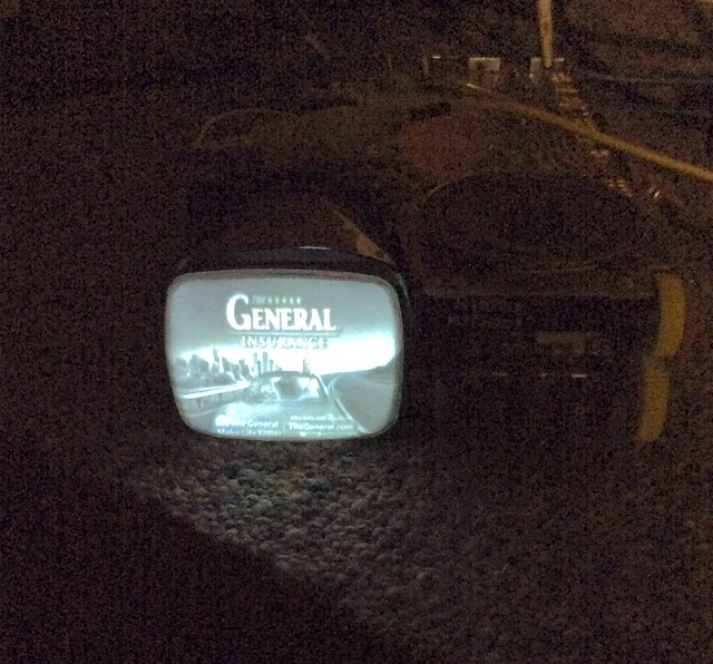 Still much work ahead, tuning voltage is low. Although I have about -34 volts to the hot end of the tuning pot, I can't get full range. (that's why I moved the converter box to ch 3 as the tv tuner was maxed out and not quite tuning the signal on ch 4.) See pix from last night. I still have not got supply voltage from either of the rear jacks to operate the set, I supply 5 volts to the "bat" terminal on the sound board to power the set. Likely more corroded open runs will be found... the tuner boards are plagued with corrosion. Fun project! jr
|
| Audiokarma |
|
#11
11-17-2017, 09:20 PM
|
||||
|
||||
|
Quote:
After checking all of the corroded traces on the tuner board which ohmed out ok, I discovered that the center pin of both the 6 and 12 volt rear connectors is NEGATIVE! Duhh! jr
|
|
#12
11-07-2017, 01:50 PM
|
||||
|
||||
|
Did you say you changed the video-IF board ? Yes there is lots of corrosion on the little brass connectors. Thanks for the pic I wanted to make sure I put the wires back in the right place although I cannot get it to work, if I had another one of those boards maybe that's the problem with this one, who knows.
|
|
#13
11-07-2017, 02:47 PM
|
||||
|
||||
|
Yes, but the main problem last night was solved by moving the converter box to ch 3... I need to figure out what is pulling down the output of the tuner pot, as it will only go to about -14 or -15 volts and will not quite tune in ch 4.
jr
|
|
#14
11-07-2017, 03:11 PM
|
||||
|
||||
|
Yes I noticed that same thing on mine tuned close to 3 the voltage is at 33 v but move it the other way and it will drop to 15 or so volts . Maybe this is how it was designed I don't know but I wish I could get a pic on mine by finding what's wrong. The thread I read from England said the same thing and he thought that the varicaps were bad, I have no clue even where they are , possibly in the tuner it's self being the 33 v goes directly to the tuner fed by the video- IF board and dropped down from 45volts via a 120k resistor and the end pin2 next to the -33 v output should show - 0-33 v negative as the tuning is moved , it's marked variable in the half ass schematic which don't give any electrical info at all.
|
|
#15
11-07-2017, 04:10 PM
|
||||
|
||||
|
Indeed the varicap diodes are inside the two tuner modules ... they are shown on the schematic as VC-601, 602, 603 and 606 in the VHF tuner module and VC-501, 502 and 503 in the UHF tuner module. I have yet to open either tuner module, so have never seen them.
If your set is no longer making sound or even a hint of a picture anymore, I would suggest that something went wrong in re-assembly after the batteries were installed... it is very easy to mis-align the Berg pin connectors, usually with disastrous results.  jr
|
| Audiokarma |
 |
|
|


 Hybrid Mode
