
|
|
|
#47
 07-28-2010, 12:03 AM
|
||||
|
||||
|
While looking thru the early pages of this thread, I think this cap and coil
 is to form a series resonant circuit to make for a low impedance at the set's RF upper midpoint frequency, around 1200KHz. So that the chassis looks like a good RF ground plane without having to use a cap too large that it produces too much of a shock hazard to the set's user. With the 0.022uF cap, it needs a 0.8uH coil and that will yield about 6 ohms of reactance. Using the coil inductance calculator at http://www.66pacific.com/calculators/coil_calc.aspx and guessing 3/4 inch diameter and 1/2 inch length, I get about the 0.8uH value and thus the 1200KHz resonant frequency. Not completely sure that this is why they did this. is to form a series resonant circuit to make for a low impedance at the set's RF upper midpoint frequency, around 1200KHz. So that the chassis looks like a good RF ground plane without having to use a cap too large that it produces too much of a shock hazard to the set's user. With the 0.022uF cap, it needs a 0.8uH coil and that will yield about 6 ohms of reactance. Using the coil inductance calculator at http://www.66pacific.com/calculators/coil_calc.aspx and guessing 3/4 inch diameter and 1/2 inch length, I get about the 0.8uH value and thus the 1200KHz resonant frequency. Not completely sure that this is why they did this.  
__________________


|
|
#48
07-28-2010, 12:31 AM
|
||||
|
||||
|
Hmm - interesting. I'm not sure either, but it does have a UL sticker. I have a couple other non-UL AA5 sets without this RC combo or that R3 resistor in your schematic.
|
|
#49
07-28-2010, 07:50 AM
|
||||
|
||||
|
I was told the coil and cap combo was made to block some communications frequencies that would give am reception trouble. They didn't say wave trap, but that is what they seemed to be describing. I have my doubts about that, though.
|
|
#50
07-28-2010, 12:18 PM
|
||||
|
||||
|
The trap was to shunt to ground any strong stations that were near the set's IF frequency. When the set was built, there were powerful coastal code stations down below the broadcast band that could leak into the IF. They aren't there any more, so an ordinary .02 or thereabouts cap will do.
Edit: well, maybe not exactly. If the trap were in the RF circuits it would be for the shore stations. If you have a trap there, it is superfluous today; they often have trimmers to be set to the IF frequency. With the Philco trap on the radio in question, consider the following: http://www.philcorepairbench.com/tips/svctip37.htm
__________________
Reece Perfection is hard to reach with a screwdriver. Last edited by Reece; 07-28-2010 at 12:36 PM.
|
| Audiokarma |
|
#51
07-29-2010, 12:10 AM
|
||||
|
||||
|
That cap looks a little too big to be a 0.022 but usually those were 0.1uF. If so, then with a 1.2uH coil (7 turns 0.8 inch diameter and half inch long), it could resonate at the IF frequency. Assuming the presence of the guts of the cap inside the coil doesn't effect the inductance.
I sometimes just left it alone, as leakage in the cap in this spot in the circuit is of little consequence. Especially when there is a 120K resistor in parallel anyway.
__________________
|
|
#52
07-29-2010, 07:30 AM
|
||||
|
||||
|
How many zillions of AC/DC chassis similar to this sat on kitchen counters close to the sink, etc. etc. back in the days before lawyers and when you could (and did) stick your finger in the fan and your fork in the toaster (can still do that...hmmm....
) People used to know what they could or couldn't do, and the ones that didn't were Darwin fodder. "Our mommy told us not to put beans in our ears." 
__________________
Reece Perfection is hard to reach with a screwdriver.
|
|
#53
07-29-2010, 05:17 PM
|
||||
|
||||
|
Quote:
 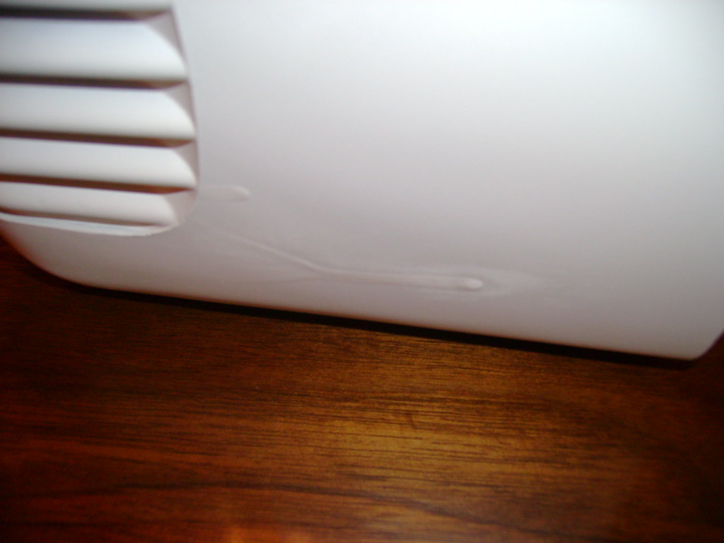 A little sanding and re-spray took care of that. Here it is with a dry run of the dial face. 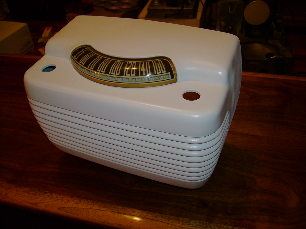 I picked up a reproduction back from Retro-Tronics in basic black. I could have payed a few more $ for a white one, but decided to just paint it myself. 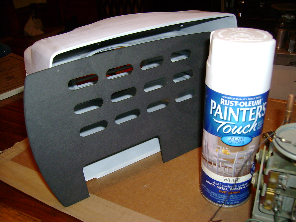  Unfortunately, I'm missing the clips. Here are some clips from another radio. Does anyone have some to spare or have any idea how to attach it ? For now I'll just wedge a little foam in a few places to hold it on.   Finally, here's the new decal. 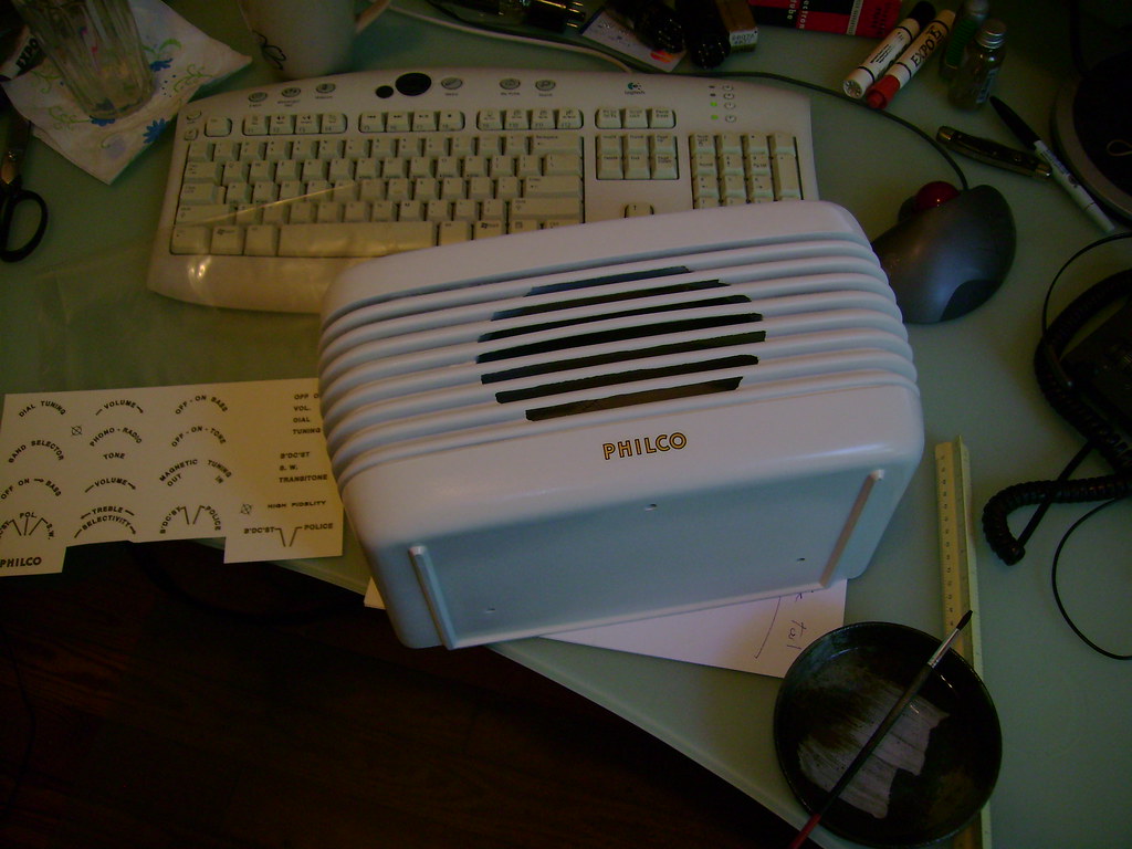
|
|
#54
08-03-2010, 09:49 PM
|
||||
|
||||
|
They're both finally done
 I scanned an original back and printed some labels for the reproduction back. 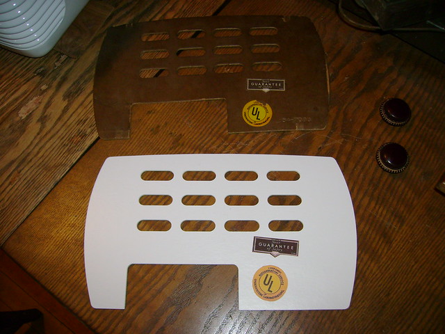 Then, glued the internal antenna salvaged from another set.  I'm using foam wedges to hold on the back until I can come up with something better. I used a white power cord to match the cabinet.  Here they are side by side.  The dial lamp in the white set is brighter and the volume is lower. I wonder if the bulb isn't right, or the tubes aren't drawing enough juice
Last edited by bandersen; 08-05-2010 at 01:11 PM.
|
|
#55
08-03-2010, 10:02 PM
|
||||
|
||||
|
could be someone mixed up a #47 for a #44 bulb. One uses 150ma while the other takes 250 both @6v. With your white set playing lower with a brighter bulb, I'm willing to bet that is what is happening.
|
| Audiokarma |
|
#56
08-03-2010, 10:44 PM
|
||||
|
||||
|
Good call. The white has a #47 and the brown a #51.
|
|
#57
08-04-2010, 12:15 AM
|
||||
|
||||
|
Swapping out bulbs helped a little, but the real culprit is a weak 7C7 tube. Time to dig through my stash.
|
|
#58
08-04-2010, 09:36 AM
|
||||
|
||||
|
I like that pair of hippos. Sneaky move repro'ing the back labels!
What does that big honkin' speaker in the background go to?
__________________
Reece Perfection is hard to reach with a screwdriver.
|
|
#59
08-04-2010, 11:54 AM
|
||||
|
||||
|
Quote:
|
 |
|
|


 Linear Mode

