
|
|
|
|
|
#1
 05-17-2011, 05:58 AM
|
||||
|
||||
|
Quote:


|
|
#2
05-17-2011, 10:34 AM
|
|||
|
|||
|
Quote:
 oc(Bill) oc(Bill)
|
|
#3
05-17-2011, 08:24 PM
|
||||
|
||||
|
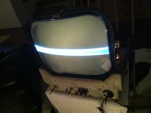
Got the new transformer in the set and it gives deflection but not a full picture. It did bring the horizontal picture back to the center again. Even though it was not a full height picture it did for the first time look "correct." It might be because I could see scan lines for the first time, or because the picture was horizontally aligned, or it could just all be in my head. I did try adjusting the vertical hold control, the vertical linearity control, and the vertical size control, all to no avail. The transformer I used was a Stancor model a-8122. The turn ratio was 1:4.2. The primary and secondary impedance was a bit different on the replacement than the schematics showed on the original. The original was 160 and 1,300 and the replacement was 170 and 940. Could the transformer still be the problem or is it time to look elsewhere?
|
|
#4
05-18-2011, 06:22 AM
|
||||
|
||||
|
Do the vertical controls do absolutely nothing to change the bar, or just that they don't get it to a proper height?
You don't mention it, but I assume you tried the lead swap on one of the transformer windings to check if the phasing was right? If you did, it's probably time to start looking elsewhere; you've got "partial" vertical, as opposed to flat-out no vertical. That would suggest an out-of-spec component - time to start ohming out the resistors in, and before, the vertical section to see if any have gone high if you haven't already done so. If those all check out fine, then it can shift the focus back to the transformer; less of a headache that way than trying to source an exact match and finding it still doesn't work. Are you able to borrow or access an oscilloscope? Those can come in handy when trying to figure out the problem, since the actual shape and tracing back of the waveforms can point to the cause relatively quickly (i.e. if the problem is caused by the vertical section, or the result of something before) ... but it can be done without.
|
|
#5
05-19-2011, 12:26 PM
|
|||
|
|||
|
To the OP:
At this point, and if you still have access to the variac, you might consider trying this: Disconnect both primary leads of the vert.out transformer and drive it directly with the variac. Granted it's a sine wave instead of sawtooth, but will tell you a lot. You should get very robust deflection, probably at around half to full line voltage. This will tell you the tranny and yoke coils are good, thereby proving the fault lies somewhere "upstream" of the tranny. If the problem remains, it's gotta be either in the tranny or the yoke (like a shorted turn that won't show up on a resistance check). Now disconnect the yoke winding and drive it directly with the variac (starting from a low setting). If deflection comes up, the yoke is good and by process of elimination, the fault would be in the tranny. Of course if the fault is "upstream" all bets are off. The first place i would look is the plate load resistor of the vert.oscillator, if you haven't already checked it. I can't see it since i don't have the schematic of your set, so this may not be applicable. But in many sets that resistor is a very common failure and worth bookmarking*. Its value goes 'waaay high due to being hammered by a high level pulse. Bill(oc) *Germaine to all makes and ages of '50s-'60s tube sets. Last edited by old_coot88; 06-09-2011 at 11:36 AM.
|
| Audiokarma |
|
#6
05-19-2011, 01:48 PM
|
||||
|
||||
|
Quote:
BTW- What is The OP? Last edited by vts1134; 05-19-2011 at 04:22 PM.
|
|
#7
05-21-2011, 12:42 PM
|
||||
|
||||
|
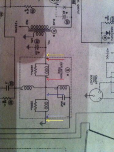
I think I need to back up and run a test that I don't think I did right before. I want to test the deflection coils to see if my problem is there. In the picture of the schematic below I tested continuity across the yellow wires. I'm not sure if that was right. I think I need to test across the red, and across the blue to test each coil. Can any one confirm that? If that is indeed what I need to do then my next problem is that I don't know how to test the two coils independently of each other. I apologize for leaning so hard on all of you to help me get this sucker up and running, but we all have to start learning some where I guess.
|
|
#8
05-21-2011, 03:01 PM
|
||||
|
||||
|
Looking at your picture, what you'd want to do is as follows. This will ensure you've tested the coils:
1. Disconnect/desolder the ground connection at the lower yellow arrow. (this ensures you test the coils themselves and not an alternate current path - note the other yellow arrow traces through the transformer and also to ground, resulting in two possible paths for the current to flow when you measure any two points in that line.) 2. Measure across the blue arrows. 3. Measure across the red arrows. 4. Reconnect the ground connection from step 1. It looks like you have resistors in parallel with your coils in the schematic. If that's the case, the resistance you measure should be 1/measurement = 1/(coil resistance)+1/(resistor resistance). Keep in mind the coil will have a fairly low resistance, so the reading is probably only a handful of ohms. With both resistor values the same, the red and blue measurements should be identical. If you measure anything different than expected, you'd need to disconnect one lead of the resistor to determine the culprit (coil or resistor) Last edited by VintagePC; 05-21-2011 at 03:04 PM.
|
|
#9
05-21-2011, 03:32 PM
|
||||
|
||||
|
Quote:
|
|
#10
06-13-2011, 12:39 AM
|
||||
|
||||
|
Aww, but that is when it is the most fun! Last new years(or was it christmas) I had a couple, and droped a Color chassis on my foot. It took me a while to realize that it cut me!... the little bugger.
Back when I encountered my first set with those bumble bee caps(it was a zenith transoceanic) I made the exact same mistake. To this day it still has those caps in it. Tom C.
|
| Audiokarma |
|
#11
06-13-2011, 12:11 PM
|
|||
|
|||
|
After you get the C49 thingy sorted out, take another look at the 6V6 output stage and see if it's "version 1" or "version 2".
With the revisions shown in the schematic, the output stage itself has seen a fair bit of engineering fudgery, probably to optimize linearity. In "version 1" the plate and screen (pins 3 and 4) were simply strapped together. Kind of unusual. In "version 2" the screen is supplied from B boost (again kinda unusual), through added-in resistors R96 and R97. Cap C69 is added from the plate to screen, probably to tailor the waveform. And bypass cap C71 is added to filter the boost line. If your set has "version 2", those two caps should definitely be replaced if not already. And the two resistors checked for value. oc
|
|
#12
06-18-2011, 07:22 PM
|
||||
|
||||
|
Because I'm not afraid to look like a rookie here, and in the hopes of teaching some one else, I'm going to tell you what I didn't do. I didn't test the tubes in this set (except the two vertical tubes, and even then I don't think the tester was good) until today. I know some of you will be thinking
 , I am thinking . My new rule is tubes will be tested before I even begin recapping. Ten tubes were shot... 10! I came home to replace the tubes in question and found two things. #1- my set uses V10 and I don't have a 6AT6. I had a 6AV6 left after replacing all of the other tubes. I'm not sure if I had a mix up at the shop when I was replacing tubes, or if a 6AV6 was in V10 in the first place. At any rate I simply left V10 out and fired the set up. #2- When I give the set more than 90volts I start to hear a sound in the high voltage cage that I don't like. The sound get worse as I cranked voltage higher. It kind of sounds like a very faint snap...snap...fsst...crackle...fsst..snap...crackl e. It could just be a different sound and I'm paranoid but it sounds like something is eating itself. I don't know how to test such a thing as I can't tell exactly where it's coming from. I'd rather not "test" by waiting until what ever it is to finish eating itself and whatever other components around it that it wants to take with it. Any thoughts on what the noise could be? , I am thinking . My new rule is tubes will be tested before I even begin recapping. Ten tubes were shot... 10! I came home to replace the tubes in question and found two things. #1- my set uses V10 and I don't have a 6AT6. I had a 6AV6 left after replacing all of the other tubes. I'm not sure if I had a mix up at the shop when I was replacing tubes, or if a 6AV6 was in V10 in the first place. At any rate I simply left V10 out and fired the set up. #2- When I give the set more than 90volts I start to hear a sound in the high voltage cage that I don't like. The sound get worse as I cranked voltage higher. It kind of sounds like a very faint snap...snap...fsst...crackle...fsst..snap...crackl e. It could just be a different sound and I'm paranoid but it sounds like something is eating itself. I don't know how to test such a thing as I can't tell exactly where it's coming from. I'd rather not "test" by waiting until what ever it is to finish eating itself and whatever other components around it that it wants to take with it. Any thoughts on what the noise could be?BTW the vertical is now full height. Sorry to all of you here for wasting trouble shooting time by not completing step one.
|
|
#13
06-18-2011, 08:11 PM
|
|||
|
|||
|
The 6AT6 and 6AV6 are interchangable. if the 'V6 is good just leave it in.
Do you smell anything burning, or smell ozone? Is the aquadag (conductive coating) on the CRT securely grounded? Hey, you didn't waste anybody's time so don't feel bad We all enjoy the heck outa this stuff no matter whut.
|
|
#14
06-18-2011, 08:38 PM
|
||||
|
||||
|
Quote:
I may not have wasted any ones time, but it was a forehead slapper for me that's for sure. It sure has been a learning experience on my first set.
|
|
#15
06-19-2011, 07:40 PM
|
||||
|
||||
|
It doesn't look to me like your CRT has any aquadag coating on it - not all do. I bet there's a high voltage capacitor next the the rectifier tube that does the filtering.
The arcing could be caused by component leads or wires coming too close to the base. I recently worked on a Motoorla that had bad arcing caused my a wire coming too close to the rectifier. All I had to do was move it out of the way. Did you do any work around that area ?
|
| Audiokarma |
 |
|
|


 Hybrid Mode
