
|
|
|
|
|
#1
 11-09-2019, 12:19 AM
|
||||
|
||||
|
Okay, here's the service manual. For those who want it I'll keep it up for a week and then for the sake of my dropbox bandwidth I will have to take it down, so grab it while you can! It's a 30mb pdf.
https://www.dropbox.com/s/wbe2wsi7hh...00svc.pdf?dl=0 
|
|
#2
05-19-2020, 05:35 PM
|
||||
|
||||
|
Quote:
I removed the ACRY unit and examined it. According to the service manual, there should be 120VAC at the transformer connection, but I am only measuring 47VAC. So, I started looking at individual components (which are practically impossible to find today, though I did just find yesterday a 25 pack of the KC103P capacitors on eBay). The capacitors appeared to test ok. The relay, when i plug the board into the wall, did not click, however I did desolder it and manually connected it to my motorcycle battery and it at least did click then (Ive ordered a replacement that matches the pin layout and the specs, minus the TV rating). I desoldered the diode and it tested ok. I then desoldered the induction coil (L50 on the board) and it tests at or around zero, which indicates it is bad. So, my question is how do I determine what an adequate replacement part would be for it? There are no specs marked on it, only what appears to be a part number which turns up zilch in a google search. The service manual does not list this part for the ACRY unit, but it DOES list a filter (denoted as F50 in the manual, despite the fact there is NO F50 on the board), so I was thinking maybe this was a typo because an induction coil can be considered a filter. so, the service manual lists this "filter" as part number DTF1012. At pacparts they have a listing for that part, and the order page for it says it is not in stock, but is available for order. I ordered the part yesterday morning, but today was issued a refund because **surprise!!** the part isn't ACTUALLY available. So, I'm stuck and at a loss. Do any of you have any suggestions?
|
|
#3
05-19-2020, 06:50 PM
|
||||
|
||||
|
If I am remembering inductors correct, a resistance at or right next to 0 is fine.
I'd be verifying that it's not the transformer at fault as you know the wrong voltage is comping out of it, but you didn't say what was going in. I believe the tap numbering is listed in the service manual. Also verify your entire bank of fuses are good with a continuity check. Sometimes when I get weird voltages on a feed circuit it's a cartridge fuse that's gone bad.
|
|
#4
05-20-2020, 01:17 PM
|
||||
|
||||
|
Quote:
I have not checked all fuses on every board, but only the one fuse on the ACRY board. Continuity on that fuse checks OK. I attached an image. The posts in the red square are where I tested and showed 47VAC rather than the 120VAC as stated. That CN550 connection is where the transformer attaches. Last edited by cornponious; 05-20-2020 at 01:24 PM.
|
|
#5
05-20-2020, 01:32 PM
|
||||
|
||||
|
Quote:
And here is the inductor in question. I can't even find any information online for how to determine the inductance of this coil, regarding the specific text on the side. Nothing I have found seems to match the type of text on the inductor. And there are no other markings anywhere on this inductor. It's very confusing to me.
|
| Audiokarma |
|
#6
05-20-2020, 06:48 PM
|
||||
|
||||
|
I mean, if the inductor was shorted between windings you'd know of it pretty quickly as that's high current 120v.
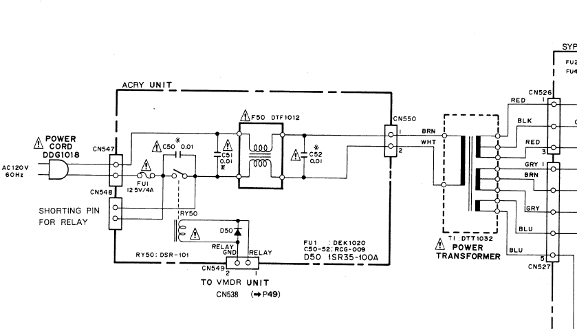 I am assuming you have the relay bypass jumper installed when testing? Otherwise your circuit breaks at the relay.
|
|
#7
05-22-2020, 01:28 PM
|
||||
|
||||
|
Quote:
You shouldn't assume. I'm just a step or two above novice. :-P No, I am not shorting the pins. So, I should do this when the board is not installed in the unit and I'm testing? Should I short it when the board is plugged in to the wall? It's just something I'm not familiar with and I apologize for coming across so ignorant. If I'm wrong here, would you mind explaining to me the process of using this shorting pin, and when I would use it? Also, where did you get that diagram? I did not see that in the service manual. I guess I could have missed it though. Also also, thank you for taking time to converse with me about this. I'm just excited about owning this, and really want to get it working. I'll short those pins and then report back what I find.
__________________
I have a stupid motovlog. It's really stupid. Please subscribe (if you want). I'm begging. The MotoDork Last edited by cornponious; 05-22-2020 at 01:33 PM.
|
|
#8
05-22-2020, 08:39 PM
|
||||
|
||||
|
Not a problem. Any pool of knowledge is better than seemingly yelling into the void.
 The diagram is near the back of the service manual mixed in with the PCB layouts. The jumper bypasses the need for the CO-V300 or similar to be attached. It delivers the voltage which closes the relay and allows the autochanger to power on. Without the controller attached or powered on the relay can't close so the jumper just bypasses the relay entirely.
|
 |
|
|


 Hybrid Mode
