The 9L37 chassis used in the Holiday and barberpole Predicta has a different vertical tube (10DE7 vs. 6DR7) and the value of that resistor in the vertical feedback couplate is different.
In that chassis, the couplate is named K4 (Sams) and the resistor is 150K.
In the 10L43 chassis in this 17-inch Siesta, the couplate is K5 (Sams) and the resistor is 68K.
The Sams and Philco manuals for chassis 10L43 agree on 68K for this resistor. Here's a snip of the Philco schematic, where the feedback couplate is named N2:
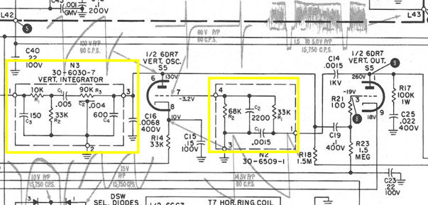
I've read competing theories on how to build the R3/C2 resistor/capacitor part of the vertical integrator couplate (N3 in this Philco schematic). One school says to put a .002-mfd cap on either side of a 90K resistor. That's what I did. Another school says to use two resistors equaling 90K and three capacitors equaling .004 mfd, one on each end and one in the middle, so the circuit looks more like your traditional vertical integrator.
Both schools claim that their version works, so I wonder if the difference is really important.
In all of the couplates that I've made, I put components on both sides of the perf board, so you won't see them all in a single photo.
Regards,
Phil Nelson