I was going to mention the portapotty circuit Tom (because I consider it a bit of engineering genius, whose ingenuity lies in its simplicity), and since the local subcarrier oscillator is the next logical step to this we may as well discuss it now.
*break*
Because the subcarrier needed to decode the new chroma information is suppressed (AKA not included as a continuous wave) at the transmission site, it must be regenerated in the receiver and locked in frequency and phase with the chroma signals so that the correct colors are reproduced. Without a frequency/phase locked local signal, colors would wash across the screen in no discernible order or the set would not produce any colors at all. In fact when the local oscillator is not locked in correctly, it produces what can be described as a 'rainbow' effect of colors dancing across the screen. This is a frequent mode of failure with color sets, and immediately alerts the technician that the trouble lies somewhere in the 3.58Mhz local oscillator circuit or its accompanying reactance circuit (the one responsible for 'nudging' the local oscillator into alignment). Either the incoming burst is not being compared correctly with the signal generated in the local oscillator, or there may be some sort of trouble with the stability of the circuit itself- either the crystal has gone bad, or there is an out of tolerance component or bad tube somewhere. But I digress...
As I stated before instead of always transmitting the subcarrier, it was decided to only include a short period or 'burst' of that signal in the correct phase and have a local oscillator locked to that so the signal could be regenerated locally. Coincidentally, this is where the term 'color burst' comes from. This saved much bandwidth in the transmitted signal, but moreover, did not interfere with existing standards which allowed the millions of B&W sets already in use to go on blissfully unaware that anything had changed at all- they don't even notice that a color burst exists after the horizontal blanking pulse, because the circuits necessary to do anything with it are not part of its design. In short, the signal is ignored and passes right through it.
Additional segway: the chroma information transmitted in color broadcasts *can* produce some visible artifacts in B&W sets with enough bandwidth to 'see' the 3.58Mhz chroma information without actually decoding it; namely sets produced before around ~1955 or so. This shows up as nearly impossible to see 'dot crawling' vertically through the picture, but will normally not even be noticed at normal viewing distance.
http://en.wikipedia.org/wiki/Dot_crawl
Later B&W sets had their brightness circuits bandwidth limited intentionally, so as to curtail response before 3.58Mhz where the chroma information resided. This had the effect of eliminating or at least greatly reducing the dot crawl, but at the expense of slightly reduced luminance detail. Most of the viewing public was blissfully unaware of this, but the differences can be seen with the naked eye when viewing a side by side color transmission on a B&W set with a limited luminance channel and one without such limitations (full luminance response should be around 4 Mhz before the advent of color transmissions, but was curtailed on later model sets to reduce dot crawl).
Anyway here is what, in technical terms, the color burst actually is and where it's located in the video waveform.

Compare this with a monochrome (B&W) transmission, and you can see what was added to allow the color receiver to decode the additional information.
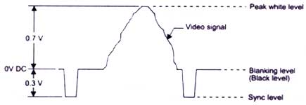
As you can see the 'color burst' is actually a series of sine waves, located after the horizontal timing pulse. There was an unused space after the horizontal timing pulse before the start of active video, in the form of a 4.7 microsecond pause. This space is where they chose to insert the 'color burst', which works out to be approximately 8 to 10 cycles of the correct phase 3.58Mhz subcarrier (sine wave) needed to decode the chroma information.The NTSC specification reads as follows:
"The color picture signal shall correspond to a luminance (brightness) component transmitted as amplitude modulation of the picture carrier and a simultaneous pair of chrominance (coloring) components transmitted as the amplitude modulation sidebands of a pair of suppressed subcarriers in quadrature having the common frequency relative to the picture carrier of +3.579545 mc ± 0.0003 per cent with a maximum rate of change not to exceed 1/10 cycle per sec."
To break that down to something the average person can understand, the coloring information was transmitted at 3.58Mhz above the picture carrier frequency (which is a function of whatever channel you happen to be tuned to). 3.58Mhz is the center frequency of the chroma information, with approximately 1.5Mhz below that and .5Mhz above as sidebands.
