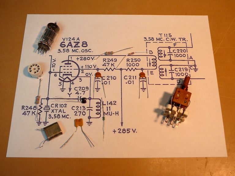
Okay, here's the breadboard circuit "before" photo:
Here is the completed circuit lashed up to my CTC-4 chassis. Judging by the scope and my handy SW radio, the breadboard circuit does oscillate around the right frequency. The first photo shows the output at terminal F of the transformer:
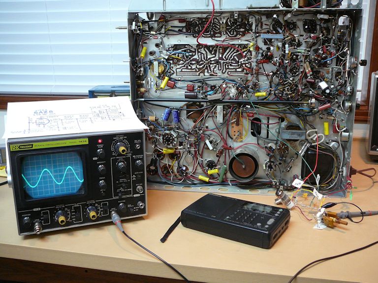
This photo shows the output at terminal A. Note that the new transformer's labeling is slightly different (terminals A and D are reversed).

Just as with the original transformer, one output is a simple sine wave and the other is a little more complex.
Touching my DMM's probe to pin 6 of the oscillator tube in the breadboard circuit instantly kills the oscillation, so that little mystery is cleared up.
I have to run out for some errands. Later on, I'll try to measure the amplitude of the signal coming out of this transformer. I can also adjust the slugs to see how they affect the output, and try whatever else seems sensible.
Phil Nelson