While messing around with the breadboard circuit, it occurred to me to use the scope to look at the phase relationship of the outputs from the quadrature transformer. I was able to adjust the transformer so that they were 90 degrees out of phase, but one output was still lumpy. Perhaps not surprising, considering that the breadboard circuit was crudely built, hanging off the chassis by various foot-long leads.
I disconnected the breadboard circuit, replaced a couple more resistors around the R-Y/G-Y demodulator, and reconnected everything with the old T115 transformer in place. I also dug up a second scope probe so that I could view both outputs at once.
Whaddya know, both outputs are nice sine waves! Using the top and bottom adjusters on T115, I got them into a 90-degree phase relationship:
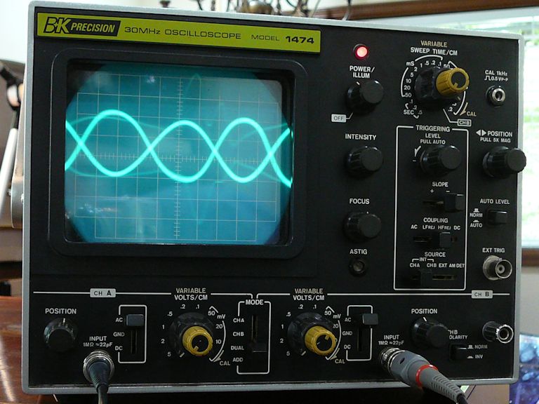
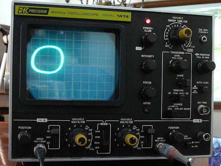
By switching the time base to channel B, I was able to get a purty-good 90-degree circle, as described in my scope manual:

This was all done without reference to other circuits or to what appeared on the screen. When I looked at the screen, I saw these color bands, which can be made to stand still:

Not a correct picture, but my goal here was to confirm that:
-- The chroma oscillator works.
-- The quadrature transformer passes the 3.58-MHz signal.
-- The transformer adjusters affect the phase relationship of its outputs.
If these things are indeed working correctly, I'll cross 'em off the list and look elsewhere for solutions.
Phil Nelson