I replaced the four corroded sand coated power resistors and recapped the horizontal circuits. I gave up on restuffing after the first two cardboard cap tubes crumbled.
There is a funky assortment of resistors like I've seen in other early 50s sets. Perhaps due to Korean war shortages plus the huge demand for TVs.
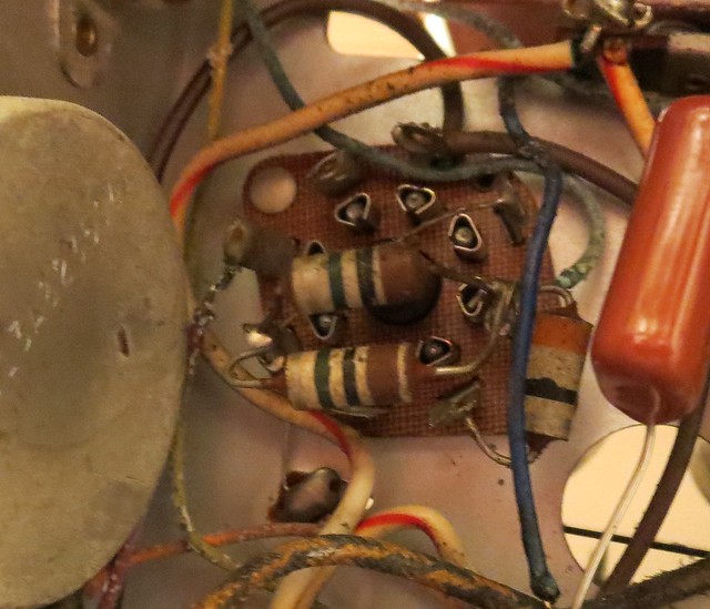
Also seeing some deviation from the schematic like this 39 ohm plus two 1M in parallel. The schematic shows a 47 ohm and single 1M. I figure it's best to stick with the values I find in the set.
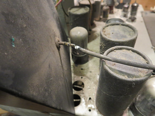
Did another power up and started hearing some arcing in the HV area. Some investigation revealed a splice in the HV lead and a dirty HV rectifier socket.
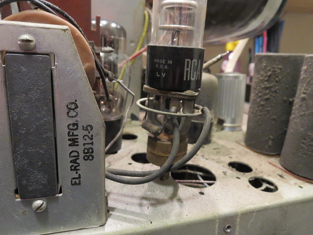
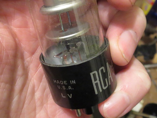
Eventually, I also discovered the 1B3 had a crack in it. Not sure if it was always there or if the arcing caused it.
With that sorted out, I finally got raster

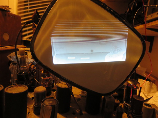
Swapped out a bunch of weak or shorted tubes and got better sound and contrast. Think I'll focus on the vertical circuits next.
