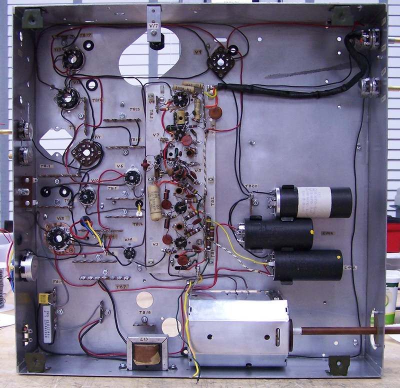
I have decided to wire the TV like the kits shows. I will use safety caps where needed and I replaced the Selenium rectifier with a 2 lug terminal strip and a 1N4007 diode. On the schematic, there looks like 300ma by the selenium rectifier. I'm guessing that either this is the rating of the rectifier or the total current draw through the rectifier. In any case a 1 amp diode exceeds those numbers by a factor of 3.
I started step 1 (Power Supply and Filament) yesterday (Monday) and finished it today (Tuesday). Some observations are in order. All-in-all the step by step instructions and the pictorial work very well and the steps are in a logical order. For instance, to wire the filament string, you start at the fuse holder then wire the first tube as in the schematic (V15), then the next wire goes to V14 and so down the filament string.
Working with 20awg solid hook-up wire can be a bit trying especially on the small 7 pin tube sockets. Those terminals are fragile! No mishaps yet.
The wire lengths given is the step-by-step are for the most part fairly accurate. There were about 6 wires where I changed the length by maybe an inch. One wire was 2 inches too long. So far this was the only big error in wire lengths. I'd rather have it long than too short. Of course I trimmed the wire to a more reasonable length. I routed the wires per the instruction sheet all within reason.
For R69 a 5 Ohm 5W resistor just at the minus side of the rectifier I used a 22 Ohm 10W sand resistor simply because that's what I had. Once the TV is up and running and with the 122Vac line voltage applied, then the resistor will be substituted for the correct value and wattage. Most likely be a gold chassis mount type resistor. You can see this resistor in the lower left corner of the chassis along with C54, the Safety cap.
Oh, yeah, I labeled each terminal strip, tube, and pot with small pieces of masking tape to help to ID the component location.