First, regarding the feed-though cap: When I say "destroyed," I mean it. Fortunately, I studied sweep alignment for two years at the Sorbonne. Unfortunately, this is not a French television set. But seriously, there's no need to despair. I want to get rid of this set as soon as I'm finished playing with it. The only way I can fail is by not doing anything at all. So, the project proceeds regardless of the outcome.
No Sharp Points?
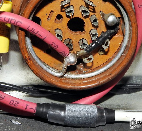
I have a healthy degree of anxiety about high voltages. Somewhere in the Sams and Rider information there's a note to avoid sharp points in solder joints on high voltage lines. I'm not sure why, but I copied the original bulky, rounded connection to the base of the HV rectifier. What might happen if there was a sharp point? I also made the high voltage cable a foot longer (temporary) with plenty of insulation at the connection.
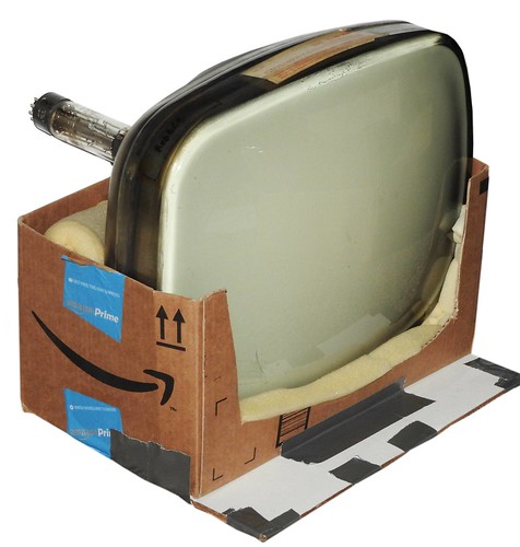
I envisioned a wooden cradle to keep the CRT securely positioned, but I found a more practical option.
I found one glitch in the tuner (besides the feed-through cap). There's no connection to the plate of the 6BC5. The circuit is open somewhere in the area shown below.

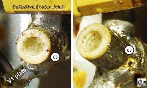
I was getting inconsistent resistance readings in this circuit for days until I found one defective solder joint. After repairing it, there was still no connection to the coil or 110V line.
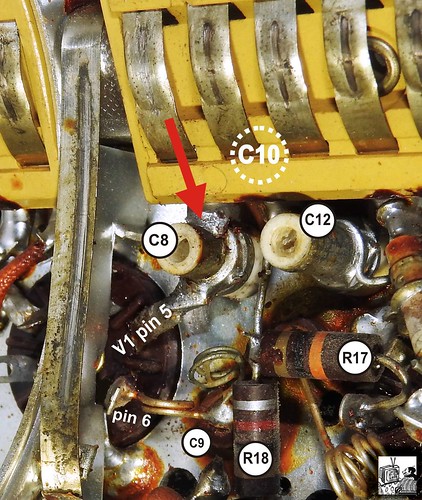
The open circuit must be between the two left contact strips in the picture, but the coil and connection are neither accessible nor visible.

It looks to me that if I can remove the single rivet, that the yellow plastic mount will slide off of the contact strips, and I'll have access to whatever is hiding behind it.
Before I attempt this, does anyone have a better suggestion?
Thanks,
Henry "The Destroyer of Caps."