I finished my voltage-testing homework, checking all the voltages against the chart in the Sams manual (
https://antiqueradio.org/art/Sams%2090-6.pdf). This spreadsheet shows the test results (ideal = voltage from the manual, actual = measured voltage):
https://antiqueradio.org/art/Emerson...nVoltages.xlsx
The tests were done with the line voltage held at 117VAC on a variac. I turned down the brightness and audio volume controls; the horizontal & vertical hold controls were set for a normal picture.
Not surprisingly, given that most of the TV works fine, most of the voltages are in about the right ballpark. The filament voltages look somewhat low everywhere, measuring about 5.7 - 5.8VAC rather than 6.3 volts. None of the other results looks like a big red flag, although possibly I'm misinterpreting something.
I'm back to seeking a cause for the bad horizontal linearity. As mentioned earlier, adding a cap across the width coil increased the width and somewhat affected the linearity, but it wasn't a miracle cure. I suppose I could go back and fiddle with different values for that cap.
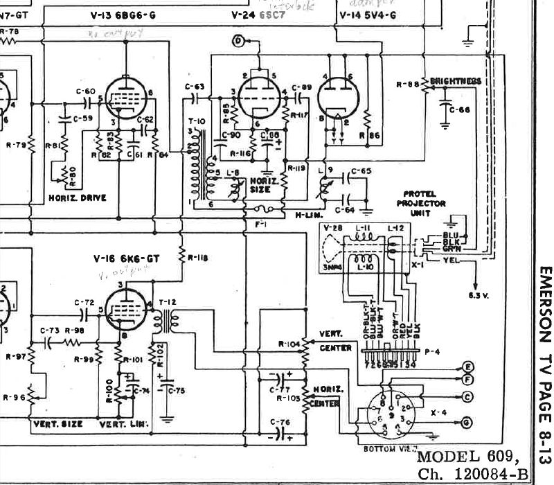
There isn't much else to tweak in that circuit, although I see two caps on either side of the horizontal linearity adjuster (C-65 and C-64 in the Riders schematic below). Those wouldn't be difficult to change, if there's a reason to try that.
Any other ideas?
Phil Nelson
Phil's Old Radios
https://antiqueradio.org/index.html