UPDATE, MAY 6, 2019, DAY 279
From Mike tonight: “Greetings. The alignment was a success! And it was a real mess. Remember, images are not in focus because they are being displayed on a 21FBP22 crt and the voltage from the Westy is not quite enough to reach the proper value. The images themselves are much clearer now, and the color is much better. The jig method is telling me what I need to know for now.
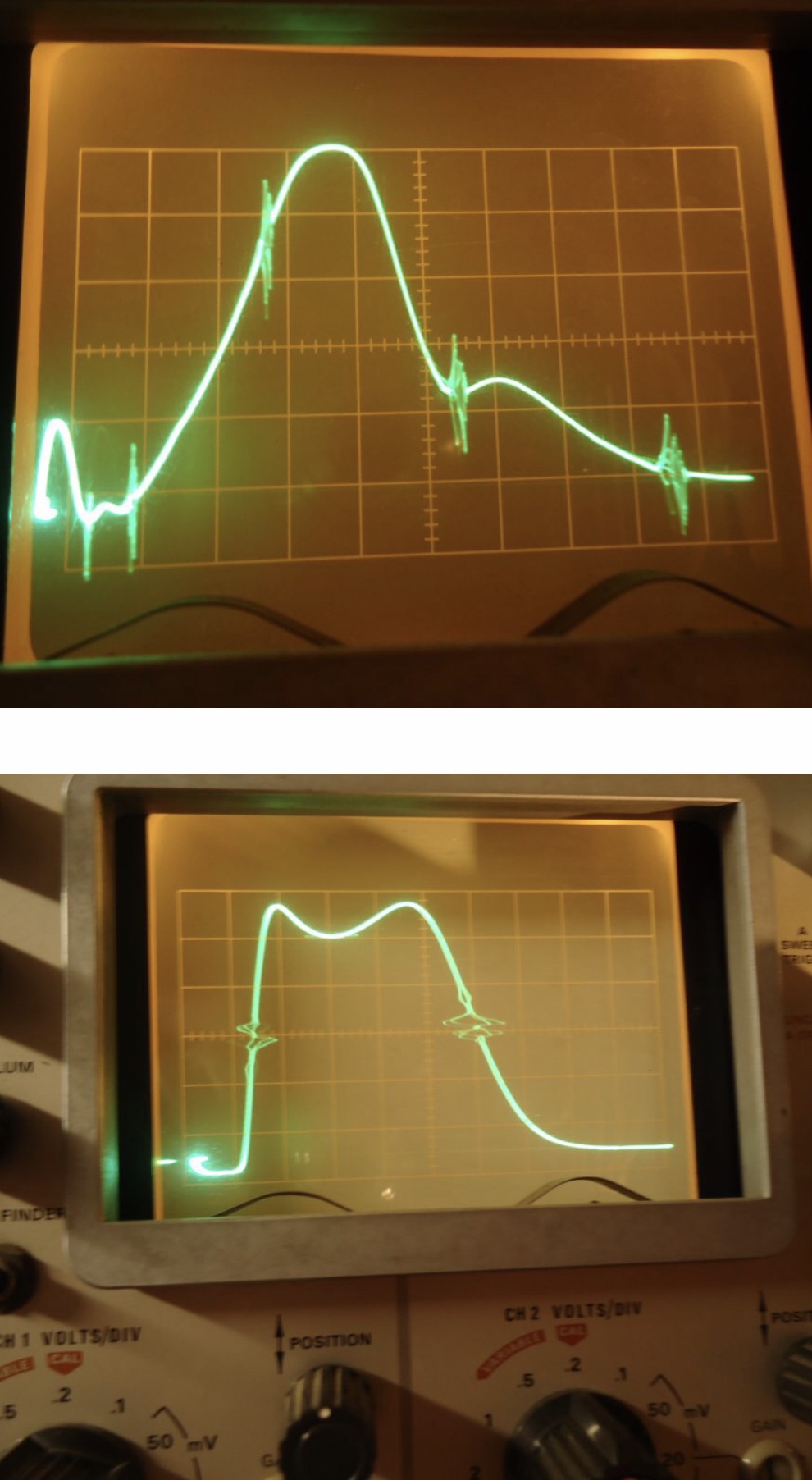
Photo #1 The alignment curve before alignment.
Photo #2 and 3 is after the alignment
Photos 4,5,6 are real time antenna tv photos.
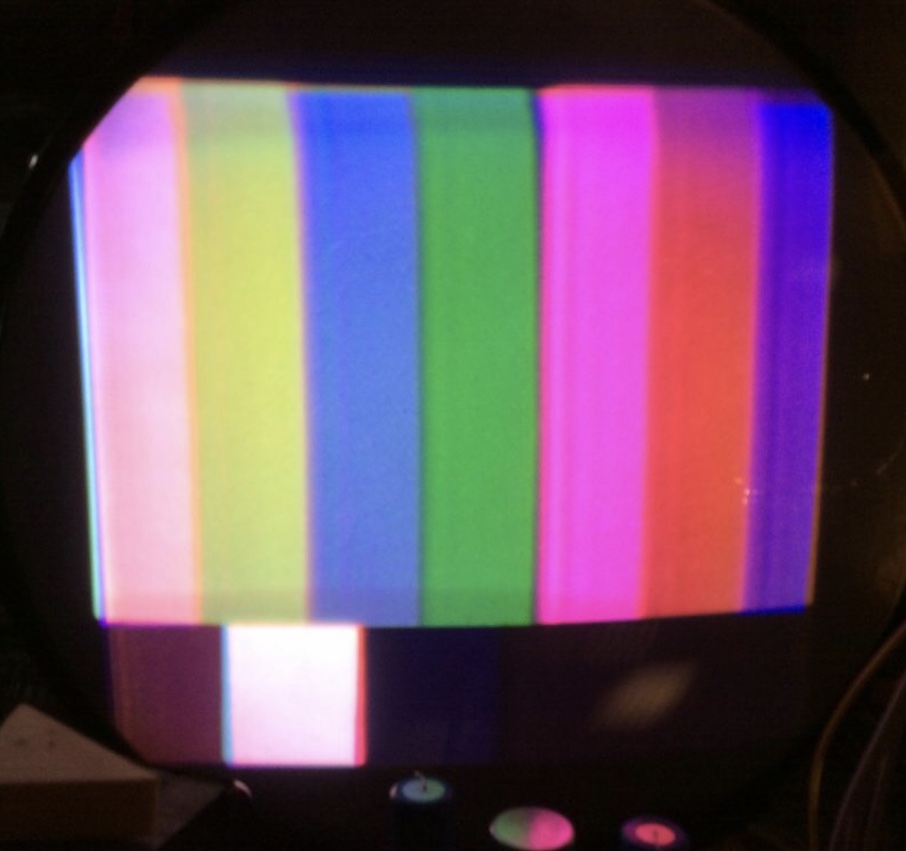
Photo 7 is a color bar pattern.
I am very happy with the results of this restoration so far.
We are getting there.
Cheers, Mike.”
Author: Looking at photo #3, half way up on the left is the CHROMA signal of 42.17 MHZ. Next in the middle of the waveform is the center of the 6 MHZ wide video signal of 44MHZ. Next, down half way on the right upper sideband is the 45.75 Video carrier and finally on the far right is the 47.25 MHZ trap for adjacent sound., as taught to me by Mike from the previous alignment of the 21CT55 chassis. What a difference from photo #1 and #3. Photo #2 is identical to #3 except flipped horizontally. A very nice textbook alignment waveform.