
|
|
|
|
|
#1
 10-26-2009, 12:27 AM
|
||||
|
||||
|
Vintage American outlet
A little off topic, but here's a vintage outlet you might find in that house that had that vintage pre-color B&W TV set.
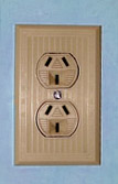 Turns out that power plugs from Australia will fit perfectly into this outlet. This one is in my mom's place, and is wired up to 240V 60Hz @ 15A. So that that Aussie plug would feel nearly at home in it, except that both current carrying pins (the slanted ones) are hot with 120VAC instead of one a neutral and the other being the hot at 240V 50Hz. This Australian radio 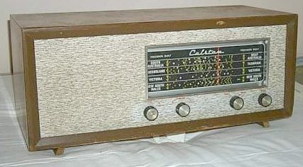 is happy with this American fed American made outlet. No Aussie TV sets though, I'd need a source of PAL for them... is happy with this American fed American made outlet. No Aussie TV sets though, I'd need a source of PAL for them...  My college dorm had outlets like these in the laundry room. This dorm, Shaw Hall of Syracuse University, was built in the early 1950s.
__________________


|
|
#2
10-26-2009, 08:14 AM
|
||||
|
||||
|
That looks like certain 220V air conditioner outlets, but you never see them as a duplex receptacle.
Here's one I found NOS made to provide power and antenna/ground to a radio, complete with special plug for the RF connection. Note the plate intended to keep the A/C and RF wires separated in the receptacle box. Wonder if the NEC would swoon over this today. Reece 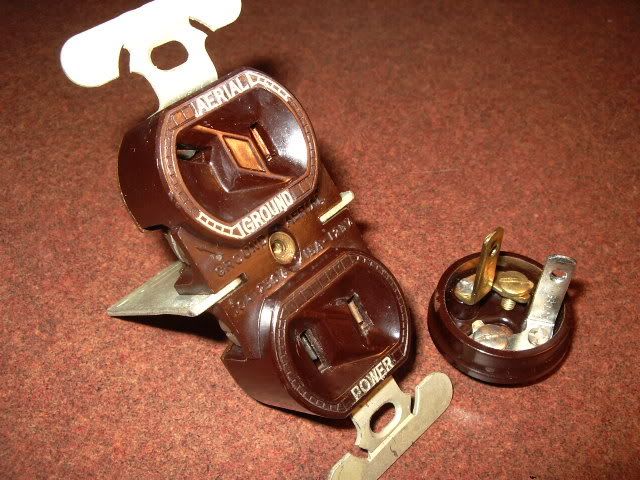
__________________
Reece Perfection is hard to reach with a screwdriver.
|
|
#3
10-26-2009, 12:00 PM
|
||||
|
||||
|
I posted this on ARF a couple years ago-never did get a good answer on why it was done this way: the old part of our shop was built in 1950, maybe earlier. All of the outlets looked like this:
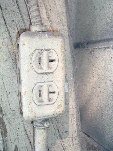 All were 120vac. I eventually switched them over to modern outlets. My Dad had coped with these by simply twisting one prong on every plug in the shop. When he added on he bought a bunch of ground adapters to make it easy to switch back and forth. Any ideas why they would use these?
__________________
Bryan
|
|
#5
10-26-2009, 01:48 PM
|
||||
|
||||
|
Most modern 20A outlets that I've seen have a T-shaped slot so regular or 20A plugs will fit.
__________________
Growing up leads to growing old and then to dying, And dying to me dont sound like all that much fun... -John Mellencamp
|
| Audiokarma |
|
#7
10-27-2009, 12:07 AM
|
||||
|
||||
|
One could guess, but this is only a guess. Extension cords and long power cords. The devices were seldom fused so the lines had to be able to handle up to what the circuit is fused for. If the 15 amp device was malfuntioning it could draw 20amps and overheat the cord. At some point they then decided that the risk was minimal and more likely to cause people to try to circumvent it.
This probably wasn't a local code issue, but they can be weird too. In one town here they decided it was a good idea to try to balance the load in homes by splitting the outlets and have the top outlet be on a different phase than the bottom. I plugged in a multiple outlet surge suppressor that used both the top and bottom outlets in parallel. The only problem is that the potential between the two live sides was now 220VAC yielding pretty impressive results when the suppressor shorted them. John
|
|
#8
10-27-2009, 04:42 PM
|
||||
|
||||
|
Quote:
plugging in two high power appliances.
|
|
#9
10-27-2009, 06:22 PM
|
||||
|
||||
|
Seems that these crowfoot connectors have existed as far back as 1916, as seen at the US Patent office http://patft.uspto.gov/netahtml/PTO/srchnum.htm, look for patent number 1179728 (type this number in the search box, and on the next screen click "images" and look at figures 3 and 4.
__________________
|
|
#10
10-27-2009, 06:38 PM
|
||||
|
||||
|
Reece, I used to work on 1945 T-2 tanker ships when I started going to sea. Everyone's room had one of those outlets with the aerial/ground connections and a normal socket below it. Looked very much like the one you show. By the time I started working there, those outlets had been out of service for many years as they were part of the original DC wiring system on the ship.
__________________
Charlie Trahan He who dies with the most toys still dies.
|
| Audiokarma |
|
#11
10-28-2009, 05:42 PM
|
||||
|
||||
|
Interesting about shipboard antenna/ground (ship's hull, I guess) connections. That radio/AC outlet and plug I found tossed in a box with a lot of other old electrical devices at a flea market. There would have been a short time, just in the 1930's and maybe early '40's, when people might have wanted to install one of these for their console radio. Most people just ran the antenna/ground wires through holes in the wall or floor, or under the window sash. Porcelain tubes were used through wall/floor in better installed exposed installations, seen them in old houses. I don't know whether this kind of receptacle dated back into the '20's, but it just "feels" '30's. Then built-in loop antennas came in and aerials came down off the roof.
__________________
Reece Perfection is hard to reach with a screwdriver.
|
|
#12
10-28-2009, 06:57 PM
|
||||
|
||||
|
Ships have a weird electrical system. Someone here might recognize what I'm describing. We don't have a hot, neutral, and ground. If you place a meter in the outlet between the two blades, you get 120 volts. If you place a meter between one blade and the ground prong, you'll get roughly 75 volts, and if you put the meter between the other blade and ground, you get about 65 volts. So, both blades are hot, but, you'd think the two blades would be 60 volts each (kinda like the two legs of a 240 outlet... each one is 120 volts). Instead, the two legs here are 65 and 75 which would add up to 140 volts... however you get 120.
A few years back, I asked the chief engineer about it, then the first engineer and second... not one of them could explain it to me!! All they know is it works as 120 when you put them together. And to think... these engineers have been there nearly 20 years! So, if any of you electrical whizzes recognize what I described, please explain it.
__________________
Charlie Trahan He who dies with the most toys still dies.
|
|
#13
10-28-2009, 10:03 PM
|
||||
|
||||
|
Quote:
John
|
|
#14
10-28-2009, 11:55 PM
|
||||
|
||||
|
Quote:
__________________
|
|
#15
10-29-2009, 12:09 AM
|
||||
|
||||
|
Quote:
__________________
Charlie Trahan He who dies with the most toys still dies.
|
| Audiokarma |
 |
|
|


 Hybrid Mode
