
|
|
|
|
|
#1
 02-12-2012, 08:32 AM
|
||||
|
||||
|
Nick, I'm sure we can get it running as a CPA set, assuming the flyback is good. There are replacements available for all the other parts, and I'm sure we can figure out the cut wires. Even if we can't find a delay line to fit in an IF can we can put a standard one under the chassis. And I'm sure Darryl can make us a converter to generate a CPA signal.

|
|
#2
02-20-2012, 02:21 PM
|
||||
|
||||
|
We'll have to figure out which route to go after you have time to sit down with the chassis, just let me know when to ship it and I'll work on getting it boxed up. Do you need the power supply along with the main chassis?
__________________
Evolution... 
|
|
#3
02-20-2012, 02:50 PM
|
||||
|
||||
|
Don't think we'll need the power supply. If we need to power it up I'm sure I have something at the museum that would work.
|
|
#4
02-20-2012, 10:21 PM
|
||||
|
||||
|
I could bring my bench supply if needed.
__________________
The world's worst TV restoration site on the entire intranoot and damn proud of it. http://evilfurnaceman.tripod.com/tvsite
|
|
#5
02-25-2012, 01:51 PM
|
||||
|
||||
|
You might see if there is some way to restore the set such that it could easily be switched between CPA and whatever state you determine that the engineers left it in. I think that having it in the last state that it worked in is as historically valuable as having it work as a CPA set.
|
| Audiokarma |
|
#6
02-25-2012, 03:29 PM
|
||||
|
||||
|
It would be interesting to see what a CPA set is capable of, and Darryl has said he can program a magic box to output that standard. I think we should at least try it, for S&G's. After that, it will probably end up as an NTSC set.
__________________
Evolution...
|
|
#7
02-26-2012, 12:14 PM
|
||||
|
||||
|
Here is what I'd to. To get it working as a NTSC set:
1. Finish documenting the chassis as it is. 2. Figure out what it needs for power supply voltages. 3. Figure out how to connect the cut wires. 4. Determine what parts are missing (delay line, etc.) and find replacements. 5. Fire it up as a NTSC set and see if it works. Make whatever alignment changes are necessary to get a NTSC picture. Then, configure it for CPA 1. Design the missing CPA circuits and install the components. 2. Fire it up as a CPA set and make whatever alignment changes are necessary for CPA.
|
|
#8
02-27-2012, 11:47 AM
|
||||
|
||||
|
Hi All,
I have been away and I have been reviewing the documentration we have collected in recent months regarding CPA. Upon comparing Nick's prototype and the RCA patent for the CPA switching, there are striking similarilties in the components. The CPA transformer and components around it in the prototype follows the patent even down to some components. I am trying to derive a reliable field switcher using only four triodes (the two 12AU7's). This is proving a challenge because one pair of triodes would provide the bi-stable device for alternate fields, one triode for field recognition, one triode for alternate field bi-stable switching and an extra triode as the field pulse buffer (as shown in the figure 13 Hazeltine drawing). The field pulse buffer is the fifth triode so the question to ask is: is there a spare unused trode on the chassis besides the two 12AU7's? Or is there possible a spare low impedance winding on the vertical output transformer which could produce the pulse? Also the transformer on the plate circuit of the 6U8 3.89MHz oscillator buffer appears redundant. The CPA transformer is all that would be required and I wonder if it originally attached to the buffer plate directly? I find the separate subchassis for the oscillator curious and wonder if it was later fitted to fulfil subsequent modifications? In the timeline of development of CPA with symmetrical vestigial sideband chrominance channels thru to the development of the IQ asymmetrical sideband solution, I suspect there were intermediate but "unofficial" modifications to the system. If I were in their shoes in 1952 when CPA with the 3.89MHz subcarrier operation was proving difficult to tame and growing unpopular, I would have been inclined to experiment with CPA back at 3.58MHz. The benefit of 3.58MHz CPA would be to make each chrominance channel sidebands more symmetrical to help reduce the CPA flicker. Introducing the IQ solution would mean different bandwidth I Q chrominance channels which would mean a second delay line for the I channel. At this stage they may or may not have thought about the design of a "simplified" narrowband chrominance channel decoder. Without seeing any evidence means that discussion of this is pure conjecture. Making the set a switchable 3.58MHz CPA/non-CPA receiver would not be much of a problem but full IQ demodulation I feel would be out of the question. I plan to complete my diagram in Visio which I will hopefully tonight. Any thoughts, comments or criticisms are most welcome. Terry Last edited by Penthode; 02-27-2012 at 08:13 PM.
|
|
#9
02-27-2012, 02:09 PM
|
||||
|
||||
|
Quote:
Pete
|
|
#10
02-27-2012, 02:51 PM
|
||||
|
||||
|
Terry,
There is a 12AX7 and 12AT7 near the vertical section. One of them is for the convergence, but we don't know what the other one does. I suspect you have a total of 5 triodes to work with. When I get the chassis the first thing I'll do is trace those circuits.
|
| Audiokarma |
|
#11
03-16-2012, 07:06 AM
|
||||
|
||||
|
Here is an article from 1952 about RCA color. Nick, could this be the cabinet your chassis was in?
www.earlytelevision.org/color_tv_today.html
|
|
#13
03-19-2012, 11:21 AM
|
||||
|
||||
|
Steve,
Proto set is on it's way to your door, I shipped it this morning. USPS w/insurance and tracking. I secured it inside the box as well as possible, hopefully they don't manhandle it. I put stickers all over it, so it's pretty obvious the contents are fragile. Nick
__________________
Evolution...
|
|
#14
03-25-2012, 09:35 PM
|
||||
|
||||
|
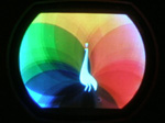
I made a CRT adapter mask to mate the proto CRT to a CT-100 cabinet, for the purpose of ETF demonstration. It's a board with trimmed 16" B&W mask secured to it, the board has mounting slots cut into it that are correct for the CT-100 cabinet so no modifications are needed. No hole drilling on the cabinet, just R&R the 15G with the proto stuff. I have also decided that having the bare CRT face in the cabinet could be a liability, so for safety's sake I will have a piece of plexiglass cut to the size of the opening in the cabinet to protect wayward fingers from getting zapped. This is what it looks like.
__________________
Evolution...
|
 |
|
|








 Hybrid Mode
