
|
|
|
|
|
#1
 01-22-2008, 04:48 PM
|
||||
|
||||
|
Beginners guide to Vintage TV Restoration?
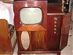
I'm looking for how-to and general theory resources for the vintage restoration beginner. I want to start my first restoration project on a 50's admiral TV/Radio. I've been collecting TV's and Radios for for a while now and would like to take the next step. I've got a $35 Admiral that would be perfect for this. I'm just not sure where to start. Any help would be appreciated.
Thanks Chris 
|
|
#2
01-22-2008, 07:17 PM
|
|||
|
|||
|
Well, AudioKarma is a good place to start! Welcome aboard.
You say you've been collecting TV's and radios for a while - have you done much electronic work? Have you repaired or rebuilt any radios? Do you know how to solder? Can you read a schematic? TV's are very complicated devices, and it's best not to just dive in and make a TV rebuild be your first restoration project, it might be more frustrating than you're up for yet. I would suggest starting by recapping a radio, preferably a small All American Five type radio set. That'll get you used to working in this sort of a device. But, assuming you know what you're up against, press on. Basically, TV restoration is similar to radio restoration - start by finding a schematic if possible. Here's a good way to find it - look for the chassis number of your television (not the model of the entire set, but the model number of the chassis. It should be printed on the back of the chassis somewhere). Then, punch that number into www.samswebsite.com. That'll give you the Sam's Photofact number that applies to your set. Then, you can go to your local library, the main branch, and ask at the reference desk for Sam's Photofact #xxx-x. Hopefully, they have it, a lot of libraries do. Mine does. Although one person posted that their local library threw them all away years ago. Then, you can photocopy the schematic and information. The Sam's is nice to have, since it has pictures and diagrams and instructions on how to take the set apart and adjust it. Sometimes it's not immediately obvious how to remove the tuner, for instance. Once you've gotten the schematic, and taken the chassis out of the television, put it up on the bench and clean it up, so you can see what you're looking at. With most tube type black and white televsisions, you're going to have to replace all the paper capacitors - this is just like recapping a radio. Only bigger, and much more complicated. Electrolytics are pretty important too, although it can sometimes be tough to find replacements, since TV's generally need 450volt rated filters. In TV's, it's even more important to do all work as neatly as possible, since there's a lot more stuff in there. I hope I don't have to mention to watch out for high voltage. The picture tube anode cap is several thousand volts, and B+ is in the hundreds. They're much deadlier than radios! But, before you pick up a screwdriver, tell us something about yourself, what you've done before, and what you're not sure about. I'm more than happy to explain whatever you want, but I don't want to sit here for half an hour typing about basic capacitors when it's all stuff you already know. Also, a picture of the TV you're talking about, and other info, like the model number, and a good picture of the inside will help me be able to explain what does what. (as it applies to your television). But welcome to the group! We're always glad to meet new TV collectors. There's only what, like three dozen of us wordwide... -Ian
|
|
#3
01-22-2008, 07:58 PM
|
||||
|
||||
|
Quote:
|
|
#4
01-22-2008, 09:13 PM
|
||||
|
||||
|
A couple of good books imho
Television and Radio Repairing(2nd edition) by John Markus (good basic text) Elements of Television Servicing(2nd edition) by Marcus and Gendler (more advanced repair) Last edited by bkharris; 01-22-2008 at 09:14 PM. Reason: fix
|
|
#5
01-22-2008, 10:04 PM
|
|||
|
|||
|
Quote:
 Quote:
Start simple. TV's are complicated - if possible start with a radio or something. You need to be pretty good at soldering. Be careful. TV's can be dangerous. Radios too. Especially "hot chassis" sets. Learn how to properly discharge a picture tube. That thing can store a nasty jolt long after poweroff. Take notes, go slowly. Document everything you do that you might forget - if you have to remove several parts to replace a capacitor, make notes as to what went where, make a diagram, take a digital photo, whatever. Just in case. Keep a notebook, and write down each capacitor as you replace it, or check off the capacitors in the copy of the Photofact. This will help you be sure you got them all. Capacitors are nocturnal creatures, and sometimes like to hide in warm, dark places, like inside high voltage cages and tuner housings. Double check your work - before you plug it in. It's easy to make a mistake, miswire something, etc. If you are up really late working on something and you're getting tired and start making stupid mistakes, go to bed. You'll just drive yourself nuts. Don't rely on what's installed in your set. Repairs made in the past might not have been right, component values might not be correct. Look for evidence that parts were replaced in the past. See next rule. Don't rely on the schematic. They're not always right. Sometimes there were incremental versions, production changes, slight differences in chassis, etc. See previous rule. When in doubt, repair it the way it was (provided the work looked factory), but take note of it, so that later on, if you're having problems with that section, you can go back and try the way the schematic had it. If the work looks crummy, or if it seems obvious that a part was replaced that was just the wrong value, then use what the schematic has. Take note of this, and the original value the part was, so that you can put it back if it doesn't work. If you have to make any part substitutions, make note of it. It's perfectly OK in most situations to replace a .047 with a .05, and the like, since the original parts were not too tight on spec. But write down that you did that, because later, when you're looking for something, you want assurance that you're looking at the right circuit, and if you see .047 on the schematic, while looking at a .05, you might forget that you made the sub. Capacitors are very important. Buy plenty. It's by far cheaper to order them online than it is to buy them one at a time locally. Check out justradios.com. TV's often need 1600v rated capacitors in places, and you can get those at AES - tubesandmore.com. Always buy a few more than you need of each value - either get a kit of common values from a supplier, or just round up to the next 10 or so when ordering. That way, after you get your nice TV running, and you find something else that's cool, you don't have to run out and buy caps before you can do anything with it. Resistors are cheap. Buy plenty. A kit of common values can be had cheaply from futurlec.com. They've got all kinds of useful parts too. Another good source is jameco.com. You want 1/2 watt resistors for most things in TV's and radios. You don't need to replace all the resistors like you do with capacitors, and you can probably get away with the kit of 1/2 watt resistors that Radio Shack sells. The old resistors are somewhat reliable, and tend to be OK, but check any that you have suspicion about, or that you have to half-unsolder for something else. Old resistors tend drift upward in value, especially if they're exposed to heat, moisture, or were greater than 1meg to begin with. The new ones look a bit different, but they're electrically interchangeable. Basic tools you need: Screwdrivers - flat, philips, assorted sizes Nutdrivers - 1/4", 5/16", 3/8" and 7/16" are the most common (most common being 1/4"). An adjustable wrench is nice to have too. needle noze pliers - get a little pair of these too. wire cutters, again, a little pair of these is handy to have too regular pliers soldering iron - 30 watt pencil iron for most things is good, and a 100 watt gun for the occasional electrolytic capacitor-to-chassis job. digital or analog multimeter Supplies: Assorted bits of wire - a roll of 20 gauge solid core insulated wire is indispensable, the insulation can also be stripped off and slid onto capacitor legs to prevent shorts. Solder - get regular 60/40 lead/tin solder with rosin core. Don't use plumber's acid core solder and don't use lead free solder. The acid core eats electronics, and the lead free solder doesn't actually work. Test gear that's handy: A dim bulb tester. This is just a scrap of wood with a power socket and a light bulb socket mounted on it. The light bulb is put in series with the power socket. This is handy to help as a "first test" to see if the set might have a short An isolation transformer. Finding one of these is hard for a tube TV. Arcade machines use isolation transformers for the monitor - one of these may just be beefy enough to handle the power draw of a tube TV, but likely not. I use an old medical isolation transformer I found in a scrap pile. This isn't necessary, but it's a nice safety precaution when working on hot chassis TV's. A Variac is NOT an isolation transformer, and does not provide any isolation from the mains. A variac. I don't have one of these, but I hear they're neat. Not necessary - the dim bulb tester works the same for most purposes. But, like I said, they're neat. I'll write more, and organize things better when I get time. -Ian
|
| Audiokarma |
|
#6
01-23-2008, 02:00 AM
|
||||
|
||||
|
Quote:
 So I was on Ebay and found one in New York , and now I have my own copy . There are quite a few old TV books on ebay , and they are really handy to have . The great thing with a vintage book is it deals just with tubes and equipment from that particular era . I would highly recommend any of the Rider publications , and for basic do it yourself you there were a few TV books done by Art Margolis in 1962 and 64 , I got these years ago and they were a great beginners book with lots of test pattern pics and everything in plain english . Welcome to our TV world here on AK .
|
|
#7
01-23-2008, 04:44 PM
|
||||
|
||||
|
Thanks for the warm welcome,
My vintage electronics repair experience is pretty limited, I have a basic understanding of electronics, I've done some basics like tube testing, tube socket replacement, chassis removal, and wire replacement. All on radios. I've never really diagnosed anything other than a bad tube or tube socket. I have more experience with solid state microcontroller electronics. I can read schematics and can also solder. I do understand the dangers of HV but still a little nervous about sticking my hand somewhere it doesn't belong. I have many vintage radios I can use for the learning process and have considered this. I think starting by recapping a radio is good advice. I plan on doing this while gathering info on the TV restoration. I have and have read the Antique Radio Restoration Guide so I'm good to go there. I own three TV's, a 1952 RCA Lindale model #21T227, a 50-51? Admiral Tele-Bar model #32K146 and an Admiral model #421M16N, this is the one I plan on starting with. This is one that I'm most willing to risk to my lack of experience. I Just bought this one locally for $35 and have not plugged it in yet but I'm going to assume it does not work. All the sets mentioned above have repair needs. What I lack is the basic knowledge of how the many different TV circuits work, which we all know is key to proper diagnostics. I'm hoping to find this in the soon to be purchased books. I am planning on going to the Early Television Convention this May, I live in Cincinnati so I'm about one and a half hours from the museum. A lot of the questions I had have been answered in this thread already. Please keep it coming. Chris
|
|
#8
01-23-2008, 03:27 PM
|
||||
|
||||
|
Quote:
http://www.earlytelevision.org/ I agree that a TV is not the ideal first project. Starting with a simple 5-tube radio would be a better introduction -- you can make your beginner's mistakes on that. The best TV repair books are out of print, but if you want to cut your teeth by restoring a simple radio, you could get a beginning radio book such as "Antique Radio Restoration Guide," by Johnson. A lot of the basic information, such as identifying components, needed tools & test gear, etc., is the same for TVs and radios. One caveat about reading old repair books: restoring a 50-year old TV is different than what a repairman faced in repairing a 2- or 5-year old TV. After decades, the electrolytic and paper capacitors have deteriorated, so probably all of them need to be replaced. Controls may be corroded or frozen. And so on. In the old days, a repairman could usually diagnose a problem quickly and cure it by popping in a new tube, replacing a burned resistor, etc. The rest of the TV was still fresh and didn't need any attention. Nowadays, the situation is reversed. Every 50-year old TV has a multitude of little issues, caused by aging and perhaps decades of use, which you need to deal with before it will be safe and reliable to play. That why I call it "restoration" rather than "repair." It's like finding a 50-year old car in a barn. You can't expect to just top off the gas tank and hop in for a cross-country drive :-) Phil Nelson Phil's Old Radios http://antiqueradio.org/index.html
|
|
#9
01-22-2008, 10:51 PM
|
||||
|
||||
|
|
|
#10
01-23-2008, 07:37 PM
|
||||
|
||||
|
Quote:
|
| Audiokarma |
|
#12
01-23-2008, 09:28 PM
|
||||
|
||||
|
Quote:
 It reminds me of a Crosley I got a few years ago . My advice would be if you are going to go right into working of tv's , do each lead for the capacitors one at a time , and then you will know where the other end is supposed to be connected because the old cap will still be attached . I still use this method , it saves lots of time retracing wires . kbmuri , Im glad you posted "How to Troubleshoot a TV Receiver" on ebay I was looking for a copy of it myself . I searched it a while back and no one had it . I also got one now 
|
|
#13
01-24-2008, 08:35 AM
|
|||
|
|||
|
That set you have for your first TV project actually looks like it will be a very good set to start on. It's a 50's set with a large all glass tube and a big metal chassis. The all glass tube is nice, because those have much better odds of still having their vacuum. The large metal chassis is a big plus, because it will be pretty easy to work on, comparitively, to some other sets. It will be cramped in places, but still, not too bad to work on. This set uses a power transformer, which is another nice thing - hot chassis sets are scary.
Now, I'm still reccomending you start with a radio first. But that should take a day or two. Then you can start on the TV. First thing, you need to pull the chassis out of the set. To do this, remove the knobs on the front. If this set has a flip down door (doesn't appear to, but might), check in there for knobs too. They should just pull off, but check for setscrews first. Then, from inside, disconnect the yoke plug. The yoke is the big coil on the back of the picture tube - it deflects the electron beam magnetically to scan across the face of the tube. It's attached to the chassis with four wires, that should terminate in a plug. Some of the later, cheaper sets omitted this plug, requiring that you remove the yoke to take out the chassis. This one seems to have a plug. Disconnect the connector at the back of the picture tube. Do this CAREFULLY. The base of the picture tube might not be still attached to the glass, the glue dries out over time. Hold onto the base with one hand and gently pull the connector off with the other. Disconnect the high voltage lead from the side of the tube. Since this set has sat unplugged for decades, there's no danger. But to be on the safe side, get in the habit of discharging the tube any time you disconnect this wire. It's the big scary one that attaches to the right side of the tube with a suction cup. High voltage can be stored here because the tube acts like a big capacitor. To discharge a picture tube, you should make a discharge tool. Get an inexpensive large flathead screwdriver with a long shaft and a fairly narrow driver end, and a good plastic handle. Then, take a length of lamp cord and bare both conductors on one end. You'll want to expose a few inches of copper. Twist the wires together and wrap them around the lower part of the screwdriver shaft tightly, making sure to get good electrical connection. You want to finish your wrap at the bottom of the shaft with a turn or two of the still insulated lamp cord. Wrap the shaft of the screwdriver in electrical tape, from top to bottom, leaving two inches or so on the driver end bare. Use a couple coats of tape. On the other end of the lamp cord, bare a short amount of wire (both conductors), and twist them togehter. Now, a lot of people prefer to use a resistor to discharge tubes, and they're probably right. I never did, simply because I didn't know any better. Also, it's hard to find a suitable resistor, from what I hear. I still do it without a resistor, but I'm sure others will chime in with a proper value and type to use. I think a large power resistor of one meg or larger is what's good to use. I don't use the resistor... If you want to use a resistor, connect it here, to the end of the lamp cord. Connect the other end of the lamp cord (or the other end of the resistor, if you used one) to a large alligator clip. Be sure to make good connections (solder, if possible). And wrap any exposed metal in plenty of tape. To use the discharge tool, clip the alligator clip onto the metal chassis of the TV, and carefully slide the screwdriver under the suction cup until you feel the metal spring clip in the center. If you didn't use a resistor, you'll hear a nice loud SNAP if there was any high voltage stored. Without it, I don't think you will. Do this again, just to be sure. To disconnect the anode lead, once it's discharged, squeeze the suction cup together at the top, and rock it free. You might need to peel it up to see the connection, but it's two little bits of springy metal that stick down into a hole in the tube, and clip in (kinda like the top of a christmas ornament). You just need to gently press these clips together and work them out. Disconnect the speaker, noting the polarity if it doesn't have a convenient connector. (You are making notes here, right?). Check to make sure there isn't anything else connected, some cabinets have a built in antenna, etc. Under the wooden shelf that the chassis is resting on, there will be several bolts (probably 4). Remove these. Now, you should be able to slide the chassis out the back of the set. Do it slowly, to be sure that nothing else is still connected, and that the mice haven't started to regroup. You're stealing their home, after all. Careful, it's heavier than it looks most of the time. Once you've got the chassis out, you can clean the inside of the cabinet. Check for signs of leaked tar or wax under where the chassis was, and any signs of burning in the past. Take the chassis and start cleaning it. Make a chart of all the tubes, and remove them. Watch out for the rectifier tube in the back, it's often held in with a springy clip that will constrict on the base when you pull it out. Hold this spring down to pull the tube out. Vacuum all the crud out of tube sockets, corners, etc, and clean everything real good. Careful not to damage coils, or get water into them. Don't polish the tubes with Windex. I know it'll make them shiny, but it will also take the numbers off. I've found that the best way to clean them is to run them under warm water for a bit, and gently wipe them on a cloth, like an old sock. You'll want to note the tube number first, in case it does wipe off. Depending on the tube manufacturer, the other non-number markings may come off. (GE tubes particularly). The number on GE tubes is put on with another kind of paint, and doesn't rub off as easily. If the number comes off, feel free to scrub and polish the tube all you want, then write the number back on with a sharpie. Avoid cleaning tubes unless it really needs it. If you have a tube tester, test the tubes. Note any that are weak - but remember that in a TV, a weak tube might not actually cause problems. It's best to try the first test with the original tubes, provided that they're not broken, open, or totally dead. But put the tubes away for now, you need to turn your attention to the rest of the innerworkings. Turn the chassis on it's side and look carefully for signs of damage, mouse-eating, burnt wires, missing parts, or Jimmy Hoffa. Carefully clean away any crud you find, compressed air and a clean paintbrush work well, and you can vacuum provided you're careful not to disturb anything. Figure out a way to get the chassis to stay up on it's side. Metal L brackets bolted to the original holes, clamping it to your workbench, whatever. You just don't want it to fall over when you're working on it. Look at all those wax capacitors! You need to replace them all. Before you start, take digital pictures of the underside of the chassis. Close up ones too. You want to have a reference point just in case. Using the schematic as a guide, start replacing capacitors. Go slowly, take notes, and don't be sloppy. Clipping the old capacitor leads, bending the ends into hooks, and soldering new ones onto that is sloppy. You'll actually want to, wherever possible, actually desolder the leads of the old capacitor, properly attach the new one to the terminal strip, and resolder it. Clipping and tacking works, and you might get away with it in a radio, but it looks sloppy, creates more connections, is more prone to shorting, and ultimately makes the new capacitor rely on a 50 year old solder connection that may not have been that great, and an old oxidized capacitor lead. To desolder, I like to use a desoldering pump. The blue one from Rat Shack (about 8 bucks) works well. Heat the connection with the iron, and flow new solder into it. This gets the solder melted and supplies it with fresh flux. Then, put the desoldering pump next to it and press the button. This takes practice - another reason to start on a small radio. You might have to do it a couple times, and even then you won't get everything perfectly clear. But once you can see the way the old capacitor lead was folded around, you can use your little needle nose pliers to gently unfold it, and straighten it enough to remove. Once you've gotten the old capacitor lead out of the terminal strip, clean the terminal up with the desoldering pump. Install the new capacitor like the old one was, use 'spaghetti tubing' or stripped off solid core wire insulation to insulate the leads if necessary, since the new one is smaller than the old one, there will be a large area of exposed wire - more prone to shorting in some areas. Try to only remove one cap at a time, but many times you'll need to take off three or four at a time in a TV, since there will be a couple tight together, or on the same lug of a terminal strip. This is another reason to start simple. But take notes, and you'll get it back together. Also, don't push or pull too much on a terminal strip, tube socket, whatever. Terminal strips are just bits of phenolic with metal tabs, and it's easy to break them if you're not careful. Be extra careful around coils - the open type are just wax dipped cardboard with wire, and the soldering iron can melt them. You might have to tack onto old leads here if you're not comfortable removing the old lead from the original tab. When resoldering the connection, always heat the terminal, not the solder - and flow the solder in, making sure it makes good electrical connection. Don't wiggle anything as the solder cools, this will create a cold solder joint. Wiggleing as the joint cools is, however, a great way to create a bad solder joint to make it easier to remove the old capacitor, however. A good connection will be shiny. Once again, you MUST use rosin core, lead/tin solder. Lead free solder is unsuitable for electronics, and acid core plumber's solder is a bad idea, for obvious reasons. The electrolytics are another story. Here you have to get creative. The electrolytics are the big cans on the top of the chassis. New electrolytics are smaller, and look much different. Common practice is to disconnect the original electroltyics, and connect new ones under the chassis. You might have to install a terminal strip to mount them on. Make sure the electrolytics are installed the proper direction! They have polarity. The cans are multi-section electroltyics. That means that the can's outer casing (or outer terminal) is negative, and the inner pins are the positive sides of the capacitors in the can. The side of the can will list symbols (circle, triangle, etc) that correspond to the symbols stamped on the bottom of the can near the pins. The schematic will help a lot here. Remember, replace only the paper capacitors, and the electrolytics. Leave ceramic disc capacitors and mica capacitors alone. See http://www.antiqueradio.org/recap.htm for more information on capacitors. Any time you have a terminal strip cleared out and have a resistor that's only connected on one end, check it with your meter. If it's out of spec (+/- 10% of the printed value) replace it. You can't really check resistors that are in circuit at both ends, because the rest of the stuff in the set will interfere with your readings. But don't go unsoldering every resistor - just do the ones that you run accross. Pay special attention to any resistors that are supposed to be 1meg or higher. They drift the most. Use proper rated replacement resistors. Most common resistors are 1/2 watt. The big suckers vary - check the schematic. Have fun, and if you have any questions, don't hesitate to ask! -Ian
|
 |
|
|






 Hybrid Mode
