
|
|
|
|
|
#1
 02-19-2008, 11:43 PM
|
||||
|
||||
|
picture question
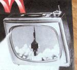
A couple of weeks ago I finished working on my 1950 Crosley tv. I noticed after it is turned off that the picture shrinks down to a little dot in the center of the screen for a few seconds and then goes dark. Is this normal?

|
|
#2
02-20-2008, 12:02 AM
|
||||
|
||||

Yes. Alot of old tv's do that. Don't remember what causes it, but, nothing to worry about.
Bill Cahill
__________________
"Tubes are those little glass things that light up orange unless there is a short.. Then they light up all pretty colors..." Please join my forum. http://www.tuberadioforum.com/
|
|
#3
02-21-2008, 11:57 AM
|
||||
|
||||
|
Quote:
When you turn it off and lose both vertical and horizontal deflection, the undeflected dot rests at the center for a moment -- I guess until the CRT heater cools off and the CRT stops emitting completely. Phil Nelson
|
|
#4
02-20-2008, 01:24 AM
|
||||
|
||||
|
Thats one of those things that makes a tv "CLASSIC"
When i restored the tv in my avatar, that was one of the first questions my older brother asked me.. "Does it have the shut-off-dot?" hehe  Steve
|
|
#5
02-20-2008, 08:40 AM
|
||||
|
||||
|
Anyone here a fan of Bob & Ray? They once did an hysterical bit on how the dot gets there.
veg
__________________

|
| Audiokarma |
|
#6
02-20-2008, 08:46 AM
|
|||
|
|||
|
On a related note, I just finished recapping a GE set with a U4 chassis (21" B&W, 1960). It worked OK before, but I replaced the electrolytics in an attempt to bring back full vertical deflection. That didn't do it (it ended up being a drifted resistor), but I did test after each can replacement. After I replaced the main three section filter, the turn-off spot became much longer lived and brighter. So much so that I'm worried about damaging the picture tube. Before, the picture would shrink into a dot on turnoff, and the dot quickly faded. Now, it shrinks into a dot and stays there - very bright. Even turning down the contrast all the way to produce a dark screen before killing the power won't prevent it (although it's less bright). The replacement caps are the same values (within tolerance) of the originals. What happened? What can I do to minimize this dot? The turn-off dot is a nice classic thing, but it shouldn't last this long, or be this bright.
-Ian
|
|
#7
02-20-2008, 11:30 AM
|
||||
|
||||
|
Quote:
__________________
Bryan
|
|
#8
02-21-2008, 09:01 AM
|
||||
|
||||
|
That brings back some memories....
In extreme cases a persistent electron beam "spot" after shutdown has left a phosphor burn mark on the screen, but in most cases the duration is not sufficient to cause harm. Some later model TVs had a "spot killer" circuit added. Perhaps a relay in the focus circuit, or cathode circuit of the CRT could provide such feature in an older set... 
|
|
#9
02-24-2008, 03:12 PM
|
||||
|
||||

Quote:
__________________

|
|
#10
02-26-2008, 07:04 PM
|
||||
|
||||
|
Further comment on the Electrohome spot-killer
Hello everyone,
Reading all these contributions, and looking back at the schematic I posted a few days ago, I remembered something. This TV was purchased by my parents in 1961, when I was less than a year old. As a child I would sometimes play with the controls, and I found that if I set the brightness to the max, the spot would not be killed when the TV was turned off, which may explain the presence of the small burn. If you take a look at the schematic, you see that when brightness is set high, the wiper of the control is grounded, so that the positive bias applied by S401 has no chance of reaching the CRT cathode. So this circuit design was far from perfect... Despite what I mentioned above, I was not too hard on this set, nor was the rest of my family, as it has survived to this day. I used to run it a few tens of hours every year but the last time I tried (last year), it was dead except for the pilot light, pointing the way to a busted LV rectifier (5V3 tube). I should start a serious restoration effort this year.
|
| Audiokarma |
|
#11
02-21-2008, 10:12 AM
|
||||
|
||||
|
I had a zenith that had an honest to god HOLE in the center where the turnoff dot is.
I've read Asian TV sets have beam killers because the Japanese are really weird about TV set operation. Some color sets would have tricolor dots/blobs on the screen after turn off...
|
|
#12
02-21-2008, 01:18 PM
|
||||
|
||||
|
My two Electrohome built TVs (1956 Viking and 1960 Electrohome) have a
section on the power switch that will apply a strong positive bias to the CRT cathode (from the B+ bus) when in the OFF position. This may have failed at some point in the past as the Electrohome (which still has its factory CRT) has a small burn spot in the center of the screen.
|
|
#13
02-21-2008, 03:54 PM
|
||||
|
||||
|
Quote:
|
|
#14
02-21-2008, 06:17 PM
|
||||
|
||||
|
Hello Old1625,
To answer your last question, I guess the following: 1 - Opening the cathode with the switch would mean routing the video signal through long wires going to the power switch, not a good way to deal with a wideband signal like this. 2 - A relay is costly. Actually, I have reviewed my schematic. The cathode bias is applied via a 220Kohm resistor connected to the wiper of the brightness control. The positive supply is also connected to the wiper through a 3.3Mohm resistor. One end of the control pot is grounded, the other one is open. As I understand it, maximum brightness is achieved with the wiper near the ground, as this makes the cathode less positive (the normal cathode D.C. voltage is given as 78 volts). As for the spot killing function, the free end of the brightness control gets connected to +135 volts when you turn the TV off, thus briefly raising the cathode voltage as I told you earlier. I have scanned the relevant section of the schematic (.gif file is about 18 kbytes). If someone could explain to me how I can post this (I am still new to this forum), it would surely help this discussion. Regards. Last edited by electroking; 02-21-2008 at 08:14 PM. Reason: minor correction
|
|
#15
02-21-2008, 06:26 PM
|
||||
|
||||
|
Here is that schematic
Sorry I hadn't read the FAQ beforehand. Hope everyone can see...
Last edited by electroking; 02-21-2008 at 06:27 PM. Reason: correct a typo
|
| Audiokarma |
 |
|
|










 Hybrid Mode
