
|
|
|
|
|
#1
 02-11-2012, 11:29 PM
|
||||
|
||||
|
CTC 11 Silvertone no Vertical
I recapped the Vertical board on my Silvertone with the RCA 11 chassis, it didn't change the lack of vertical one bit.
I also resoldered the ground lugs on most of the boards. All the resistors on the Vertical board check OK as well as the 1500 ohm wirewound that feed the B+ to the Vertical output transformer. Service switch was deoxed and tried in both positions, it's working but not the cause of the problem. I have plate voltage at pin 5 of the 6EM7 about 200 volts where it's supposed to be 165, the grid is supposed to be -35 and it's about -110. Also does anyone know the correct routing of Red & Blue wires to the Yoke? I forgot to take pictures or notes before I pulled the chassis, I think the Blue wire and the short blue jumper go to the left and center lugs and the Red goes to the right lug, or exactly opposite that, I'm guessing it would just flip the picture over if I got it wrong? 
|
|
#3
02-12-2012, 01:24 AM
|
|||
|
|||
|
Eric, if I understand your question, look to see if you have letters embossed on the plastic housing for the yoke next to each lead. It indicates the color wire for that particular lead printed next to it in the same color as the plastic housing. The letters can be hard to see sometimes. I have it on my CTC7 and CTC9 but I don't know how the 11's are set up, but maybe the letters are there.
|
|
#5
02-12-2012, 01:37 AM
|
||||
|
||||
|
Quote:
I didn't notice that on the Yoke in the TV, the back is on so I won't check now but next time I work on it I'll look. I do have the wires on correctly at least. Miniman, I don't have much experience with Scopes, I have about four of them in various condition, at least two of them should work, do I need any special Probes to do this? I also have a B&K Analyst I could drive the Vertical with.
|
| Audiokarma |
|
#6
02-12-2012, 03:20 PM
|
||||
|
||||
|
Quote:
__________________
Evolution... 
|
|
#7
02-12-2012, 04:09 PM
|
||||
|
||||
|
I've always found that X10 designation confusing. The X10 prob actually divides the signal and cable capacitance by a factor of 10. Also there's usually a trimmer capacitor on the probe or at the connector that calibrates the prob capacitance to that of the scope input. Here is a better explanation than I can do. http://www.elexp.com/t_probe.htm
|
|
#9
02-12-2012, 10:50 PM
|
|||
|
|||
|
Is the service switch in the "normal" position and are its contacts clean?
|
|
#10
02-12-2012, 11:40 PM
|
||||
|
||||
|
Quote:
I replaced a few more Capacitors today, none really have anything to do with the Vert but since it was on the bench I did them. I double checked the resistors on the Vertical board and the larger wirewounds under the chassis, all are OK, subbing the Yoke made no difference either. Checked the Height and Lin controls for continuity, they're OK as is the Output Transformer as far as I can tell, there's continuity from the red to the blue, the other three wires also have continuity between them but I'm not sure what it is supposed to be. I need to print out the Schematic for one thing, I was reading it from the PDF on a slow computer which made it difficult to find use.
|
| Audiokarma |
|
#11
02-13-2012, 02:31 AM
|
||||
|
||||
|
Success!
I took one more look at this tonight after I got done watching Rocky & Bullwinkle. I took another look at the schematic, this time looking at the Yoke circuit. I happened to notice the Yoke circuit passes through the Vertical Centering pot, this is a 3 watt wirewound that is the same type used on the Convergence board, we all know how flaky those pots can be and sure enough. The plastic knob was missing on this one, I tried to adjust it with a screwdriver and fireworks erupted, it started arcing and burning so I yanked the plug. I pried the pot off the fiber insulator it's mounted to and the insides are burnt to a crisp, this didn't just happen when I touched it with the screwdriver, this was extensive damage that took some time to do, this is probably what retired the set. So I took the Pot off the spare chassis I got from Dan (a working chassis I could have used but I want to keep the original) installed it and fired it up, this time I got a nice full raster!! 
|
|
#13
02-13-2012, 01:21 PM
|
||||
|
||||
|
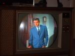
It's a reflection of the Mirror I had in front of the set.
|
|
#14
02-13-2012, 01:35 PM
|
||||
|
||||
|
I had 2 16's that either had the vertical centering or horiz centering pot do the same exact thing. Lots of sparks etc. Usually happens when it's first powered up and adjusted. The pot has been sitting in the same position for 30 or 40 years. I think they corrode due to 2 dissimilar metals touching and/or moisture etc. I repaired the last one with success but usually they are burned beyond repair. Glad you got it running. Should make a great set. They are pretty reliable once all the bugs are out.
__________________
"It's a mad mad mad mad world" !! http://www.youtube.com/user/mwstaton64?feature=mhee
|
|
#15
02-13-2012, 02:38 PM
|
||||
|
||||
|
I carried an insulated screwdriver for years in my caddy that was strictly used on these RCA's. It was funny how often the OEM control knob had burned away. I'm surprised this control lasted as long as they did.
|
| Audiokarma |
 |
|
|





 Hybrid Mode
