
|
|
|
|
|
#1
 12-23-2014, 07:06 PM
|
||||
|
||||
|
How do color signals work? An interactive explanation
Been wanting to get around to this for some time now, and I think I've finally found enough material to be able to do this in layman's terms- or at least as close to Barney style as I am likely to get!
So if you're an amateur TV repairman such as myself, you probably already grasp the concept that the RF signal carrying the actual TV information isn't any different than a regular radio transmission. The amplitude of the transmitted signal (once detected after the tuner and IF strip have done their part) corresponds to brightness information amplified by the receiver, which is sent to the CRT as video. This signal also contains various timing signals related to proper scanning of the CRT. But beyond that, how did they manage to squeeze coloring information into a signal that already had defined characteristics? The answer is: they had the space to send the information, literally in between the lines! In actuality, what the engineers did was to place coloring information in the form of quadrature modulated sine waves in between the spaces used by the brightness signals. By using otherwise 'wasted space' in the existing signal, they were able to include coloring information without upsetting the millions of black and white sets already in operation. Whoopty doo Basil, what does it all mean you must be asking? Quadrature? Sine waves? What's all this madness? I will explain. Because a black and white receiver lacks the circuitry to detect this coloring information, it will display a color program in black and white and you would never even know there was color information hidden in the signal. But in a color receiver, something almost magical happens: The coloring (chroma) signal is separated out of the brightness information right before the video amplifiers, and sent to a chroma amplifier. Then it is split into 2 paths, to recover the coloring information. These 2 paths are called 'I' and 'Q', referring to the fact that one signal is 'In phase' with the transmitted signal and the other is in 'Quadrature' or offset 90 degrees with the transmitted signal. I found a neat video that does a great job of explaining quadrature signals below. https://www.youtube.com/watch?v=h_7d-m1ehoY What are these I and Q signals being compared to, you may ask? Well, it's rather sneaky! At the transmission site there was a local signal that they were referenced to, but this signal (called the subcarrier) was not included in the actual transmitted video information! Instead a small sample of it is included after the horizontal timing pulse in the normally transmitted signal, and this short sample is used to bring a local oscillator in the receiver into phase before the start of each horizontally scanned line. This local oscillator is then used as the reference signal to which the I and Q signals will be compared. In TV lingo, the subcarrier is 'suppressed' at the transmitter, but the small sample that is transmitted is used to 'regenerate' that same signal locally in the receiver- which saved a ton of signal space. Those I and Q signals that are recovered by the color receiver are compared to the signal recovered from the local oscillator, which runs at 3.58Mhz. Differences in the phase of the I and Q signals with respect to the 3.58Mhz local oscillator represent hue information and amplitude represents intensity of the transmitted color, which are then passed to a matrix to drive the CRT. Thus by sensing the phase and strength of the recovered color information, the receiver is able to determine what color should be on the screen at any given moment and how strong that color should be. The last interesting step is that the coloring information is usually provided at the CRT grids, and the brightness information is normally provided at the CRT cathodes. Thus the CRT itself becomes a sort of mixer for the signals arriving at its respective elements, the final signal arriving on the screen in its correct proportion to provide a vivid color image.
__________________
Evolution... 
Last edited by miniman82; 12-23-2014 at 07:28 PM. 
|
|
#2
12-23-2014, 07:53 PM
|
||||
|
||||
|
This complex process is much easier to see in an actual schematic, we'll follow a CTC-2 here because it and it's sibling the CTC-2B were the only original chassis to faithfully follow the NTSC standard to the letter. All following chassis made some variation on how they went about both recovering the signal, and at what phase angle the signals were demodulated (hence other terms besides I and Q being used to describe the chroma signals such as X and Z).
The full schematic can be found on the ETF site here: http://earlytelevision.org/pdf/CT-100SamsSchematic.pdf In this first shot, we see the fist video amplifier. Brightness information is amplified and passed on to the second stage, chroma signals are filtered out at the cathode and passed to the chroma amplifier.
__________________
Evolution...
Last edited by miniman82; 12-25-2015 at 10:00 PM.
|
|
#3
12-23-2014, 08:09 PM
|
||||
|
||||
|
The signal from the cathode of the first video amp arrives at the chroma amplifier, shown here.
The signal is amplified, then sent to a bandpass transformer to ensure that only chroma signals are passed to the following stages. A form of filtering, to make sure color 'noise' is kept to an absolute minimum.
__________________
Evolution...
Last edited by miniman82; 12-25-2015 at 10:00 PM.
|
|
#4
12-23-2014, 08:34 PM
|
||||
|
||||
|
Here is where the magic happens: the I and Q synchronous detectors!
Here the chroma signal arrives at the detector's grid, where it is combined with the signal from the local subcarrier oscillator elsewhere in the schematic. The 2 detectors combine the subcarrier and chroma to provide an output to the phase splitters, which provide positive and negative I and Q signals for use in the matrix which drives the CRT. What's actually happening here is quite technical, but to sum it up the output of the pair of detectors will vary depending on the degree of phase shift between the incoming chroma signal and the local oscillator. This output voltage is a direct representation of the hue of the incoming signal.
__________________
Evolution...
Last edited by miniman82; 12-25-2015 at 10:00 PM.
|
|
#5
12-23-2014, 08:57 PM
|
||||
|
||||
|
In the phase splitters the chroma signal becomes either positive or negative, which if you recall the video from earlier make it so the signal can cover all portions or the diagram (recall him talking about +I/-Q and so forth). Then the completely demodulated chroma signal in both positive and negative forms are combined with brightness information from the video amplifier in the correct proportion by the matrix resistors, and applied to the amplifiers for each primary color.
Later receivers greatly simplified this concept by doing away with the matrix and color amp (called output) tubes by combining the signals at the CRT itself, which if you recall I said earlier turns the CRT itself into a sort of mixer. A great example of this is the simplified color receiver RCA CTC-4, which didn't even have color amp tubes! Note that there are still 'demod' tubes which use high level demod to drive the CRT directly, but I suspect that if the signals were strong enough they could have been directly applied to the CRT doing away with even more circuits. A Muntz'd design... Genius, no?
__________________
Evolution...
Last edited by miniman82; 12-25-2015 at 10:00 PM.
|
| Audiokarma |
|
#6
12-23-2014, 08:43 PM
|
|||
|
|||
|
Neat tutorial.
Another sumpthin' that would make for great discussion is - how the H and V sawtooth sweep waveforms are actually generated and appear across the yoke windings. It's easy to visualize how a neon bulb (or gas-discharge tube) relaxation oscillator generates a sawtooth (like for H sweep in very old 'scopes). But it's a bit more esoteric in TV sets.
|
|
#7
12-25-2014, 03:56 PM
|
||||
|
||||
|
Quote:
If I ran a TV station back in the late 50's to mid 70's, I would have done this in the station's color modulator. "Wow, your TV station has such good looking video". Around 1980 comb filters came out.
__________________

|
|
#8
12-23-2014, 10:12 PM
|
||||
|
||||
|
Nice 1-page explanation, Nick.
|
|
#9
12-24-2014, 02:09 AM
|
||||
|
||||
|
Definitely a good explanation. The scary thing is my principles of communication course last quarter spent a lot of time on quadrature modulation, and taught me less about it in that time then that youtube video did in under 20 minutes!
 The RCA method of building a chroma reference oscillator with feedback to correct phase errors (ie a PLL) was a gross over complication of achieving recovery of the burst reference carrier along with a color killer to switch off the color CKTs when the burst was not present...I like GE's method better: dump all that, and feed the burst to an RC tank circuit that will keep ringing until the next burst comes and use a limiter stage after it to keep the amplitude constant....It was like using the burst to strike a tuning fork, sitting back and listening to the tone. If you want to see genius simplicity Admiral made a single tube high level demodulator shown and discussed on pg 127 of the third edition of Buchsbaum's Color TV Servicing...Only lower tube count color stage I can think of is someone on here mentioning some self-oscilating high level demodulator.
__________________
Tom C. Zenith: The quality stays in EVEN after the name falls off! What I want. --> http://www.videokarma.org/showpost.p...62&postcount=4 Last edited by Electronic M; 12-24-2014 at 02:12 AM.
|
|
#10
12-24-2014, 12:44 PM
|
||||
|
||||
|
Quote:
sync system ("Synchroguide") is vastly more immune to noise. This of course does not matter to us today with signals from our local NTSC generators fed over coax. But we here still have an OTA NTSC, Ch. 39, and even at a (wideband) S/N < 1 (!) color and both syncs are rock solid on my CT100.
|
| Audiokarma |
|
#11
12-24-2014, 07:26 AM
|
||||
|
||||
|
EM; You are right, I did the same, and we did lots of graph plots, but as a technology
student vs engineering, we had some really good labs, tons of graphs (before computers) and I often made little circuits in the lab based on what I knew abour radio and tv.... If you understand how the vectors are adding, then you can visualize how each of the values add or subtract in the resistor matrix and drive each electron gun color on or off... Good of Miniman to pull this together.... Thanks, and thanks for the links to the videos, everyone can benefit from reviewing this material..... This, and other basics of tv, and radio either linked to off site, or posted here like this will surely help new collectors learn about what is going on inside the items they are collecting.... Of course it all helps that there are some really tallented youtube presenters that take the time to put together some very good movies on this stuff.... Thanks to them too! .
__________________
Yes you can call me "Squirrel boy" Last edited by Username1; 12-24-2014 at 07:31 AM.
|
|
#12
12-24-2014, 04:21 PM
|
||||
|
||||
|
I was going to mention the portapotty circuit Tom (because I consider it a bit of engineering genius, whose ingenuity lies in its simplicity), and since the local subcarrier oscillator is the next logical step to this we may as well discuss it now.
*break* Because the subcarrier needed to decode the new chroma information is suppressed (AKA not included as a continuous wave) at the transmission site, it must be regenerated in the receiver and locked in frequency and phase with the chroma signals so that the correct colors are reproduced. Without a frequency/phase locked local signal, colors would wash across the screen in no discernible order or the set would not produce any colors at all. In fact when the local oscillator is not locked in correctly, it produces what can be described as a 'rainbow' effect of colors dancing across the screen. This is a frequent mode of failure with color sets, and immediately alerts the technician that the trouble lies somewhere in the 3.58Mhz local oscillator circuit or its accompanying reactance circuit (the one responsible for 'nudging' the local oscillator into alignment). Either the incoming burst is not being compared correctly with the signal generated in the local oscillator, or there may be some sort of trouble with the stability of the circuit itself- either the crystal has gone bad, or there is an out of tolerance component or bad tube somewhere. But I digress... As I stated before instead of always transmitting the subcarrier, it was decided to only include a short period or 'burst' of that signal in the correct phase and have a local oscillator locked to that so the signal could be regenerated locally. Coincidentally, this is where the term 'color burst' comes from. This saved much bandwidth in the transmitted signal, but moreover, did not interfere with existing standards which allowed the millions of B&W sets already in use to go on blissfully unaware that anything had changed at all- they don't even notice that a color burst exists after the horizontal blanking pulse, because the circuits necessary to do anything with it are not part of its design. In short, the signal is ignored and passes right through it. Additional segway: the chroma information transmitted in color broadcasts *can* produce some visible artifacts in B&W sets with enough bandwidth to 'see' the 3.58Mhz chroma information without actually decoding it; namely sets produced before around ~1955 or so. This shows up as nearly impossible to see 'dot crawling' vertically through the picture, but will normally not even be noticed at normal viewing distance. http://en.wikipedia.org/wiki/Dot_crawl Later B&W sets had their brightness circuits bandwidth limited intentionally, so as to curtail response before 3.58Mhz where the chroma information resided. This had the effect of eliminating or at least greatly reducing the dot crawl, but at the expense of slightly reduced luminance detail. Most of the viewing public was blissfully unaware of this, but the differences can be seen with the naked eye when viewing a side by side color transmission on a B&W set with a limited luminance channel and one without such limitations (full luminance response should be around 4 Mhz before the advent of color transmissions, but was curtailed on later model sets to reduce dot crawl). Anyway here is what, in technical terms, the color burst actually is and where it's located in the video waveform.  Compare this with a monochrome (B&W) transmission, and you can see what was added to allow the color receiver to decode the additional information. 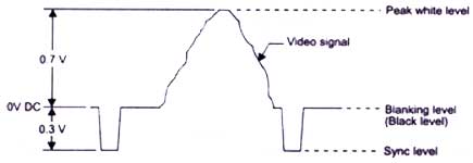 As you can see the 'color burst' is actually a series of sine waves, located after the horizontal timing pulse. There was an unused space after the horizontal timing pulse before the start of active video, in the form of a 4.7 microsecond pause. This space is where they chose to insert the 'color burst', which works out to be approximately 8 to 10 cycles of the correct phase 3.58Mhz subcarrier (sine wave) needed to decode the chroma information.The NTSC specification reads as follows: "The color picture signal shall correspond to a luminance (brightness) component transmitted as amplitude modulation of the picture carrier and a simultaneous pair of chrominance (coloring) components transmitted as the amplitude modulation sidebands of a pair of suppressed subcarriers in quadrature having the common frequency relative to the picture carrier of +3.579545 mc ± 0.0003 per cent with a maximum rate of change not to exceed 1/10 cycle per sec." To break that down to something the average person can understand, the coloring information was transmitted at 3.58Mhz above the picture carrier frequency (which is a function of whatever channel you happen to be tuned to). 3.58Mhz is the center frequency of the chroma information, with approximately 1.5Mhz below that and .5Mhz above as sidebands. 
__________________
Evolution...
Last edited by miniman82; 12-24-2014 at 04:24 PM.
|
|
#13
12-24-2014, 05:14 PM
|
||||
|
||||
|
These chroma sidebands are what is actually used by the color receiver to decode the color information. As previously stated, the chroma sine waves which are transmitted get compared to the local frequency/phase locked oscillator in the set, and phase deviations therefrom represent hue information. The strength of those same signals represent intensity, and this is how the complete color information is transmitted and received/decoded by your TV set.
 There are some very interesting ways in which the average joe technician can see these signals in action, namely by using a vectorscope attached to the color circuits of a TV set. A vectorscope is a device which gives a visual indication of the phase angle relationship between the transmitted burst and the accompanying chroma information as decoded by the set in question. http://en.wikipedia.org/wiki/Vectorscope Look familiar?  It should, it's the same exact vector diagram from the I/Q video I posted earlier! Basically the vectorscope is showing you visually the phase angle relationship of the on-screen colors (such as color bars) in relationship to the color burst, and by studying the vectorscope display you can ascertain certain things about the circuit you are attached to. Specifically if the circuit is demodulating on the correct axis (phase relationship), or if there is some phase shift which may cause the set to display incorrect colors. Most of the time these errors represent a phase shift in the demodulation circuits themselves, which usually amounts to an incorrect setting of some transformer in the color circuits. In early color receivers there is (are) normally subcarrier transformer(s) fed by the local oscillator, which shift the phase of the 3.58Mhz signal going to the demodulator tubes by a specified amount (early quadrature sets were 90 degrees, others some arbitrary amount as specified in the schematic information- so called X and Z demodulation). If this transformer is out of whack, color bars will be abnormal. Here is a shot of the subcarrier circuit of the CTC-2, and its accompanying subcarrier transformer. As you can see, the incoming burst is applied to a reactance tube. The function of the reactance tube is to compare the incoming burst to the phase of the local subcarrier, and 'nudge' it into phase so the signals match each other. It does this by varying the load on the crystal. This is exactly the same function as the horizontal phase discriminator (AFC) in some other sets (Admiral and Dumont notably), besides the lack of a crystal (horizontal circuits do not require the same level of stability as do color circuits). See the following schematics for similarities: http://earlytelevision.org/pdf/Admiral_20A1_Sams_77.pdf http://earlytelevision.org/pdf/dumon..._schematic.pdf Vectorscopes can be bought on auction sites for very little cash, I bought a Leader unit for less than $50 recently though I have yet to try it out as my daily runner (Director 21) has some RF issues I need to sort out before I delve into the chroma circuits.
__________________
Evolution...
Last edited by miniman82; 12-25-2015 at 10:00 PM.
|
|
#14
12-24-2014, 05:27 PM
|
||||
|
||||
|
Quote:
__________________
tvontheporch.com
|
|
#15
12-24-2014, 06:28 PM
|
||||
|
||||
|
Can't see it too clearly, but that's what I'm talking about.
I had a Philco split chassis set (51T-1634) with full 4Mhz luma channel that had horrible dot crawl, it was produced around 1951 or so before the advent of color transmissions. I used it to watch the nightly news for a couple months before I sold it, but the dot crawl was to me objectionable. Too bad, as that set had the most razor sharp picture I've ever seen in a monochrome set. I suppose I could have fed it with the Y line from a DVR which would have been free of any chroma mess, but it's in the past now. Oh well, I'm a color guy now! Which brings me to color traps: The filtering of any residual 3.58Mhz chroma signal in the luminance line, which further serves to reduce dot crawl in color sets. All color chassis I've come into contact with have a trap tuned to 3.58Mhz in the luminance line after the first video amplifier tube, whose purpose is to remove any residual chroma stuff left over after the first stage (the purpose of A31/L30 in the CTC-2 schematic). If this trap is tuned incorrectly, it's possible to have a mess of a picture on screen in your vintage color TV. The solution of course is to sweep the offending trap and tune it to the correct frequency, thus eliminating any residual 3.58Mhz noise present in the Y line. Most technicians these days have no idea what I'm talking about, so I will elaborate. A sweep alignment setup is used in TV servicing to pinpoint circuits in the receiver which have a defined frequency setpoint, and ensure that they are tuned correctly. This usually takes the form of a dedicated sweep rig, with sweep generator, marker, and o-scope/detector to see what you're dealing with. This sounds complicated (and it is), but thankfully the good folks at B&K were kind enough to create a rig which does all of the above in one neat little box: the 415! http://www.radiomuseum.org/r/dynasca...rator_415.html This ingenious little device incorporates 3 distinct pieces of test equipment into one box, thus greatly simplifying the testing of most receivers. It has a sweep generator, marker, and also has inbuilt chroma detection circuits for use with the probe that's supposed to come with it. The only other thing you need is a scope (and possibly a auxiliary bias box, though the 415 has 3 bias supplies in it). Basically everything is outlined in the instructions. You connect the device to your antenna terminals, and the necessary signals are passed to the chassis for use with the various probes. In this way you can set up the 415 to align a tuner, IF strip, chroma demodulators, traps, and just about any other thing you may come into contact with in your servicing endeavors. It's been an indispensable tool for me, I highly recommend it to anyone servicing sets color or not. It took me roughly 2 weeks to understand how to align the CTC-2 tuner and IF strip with it, if that means anything. I've had requests in the past to explain tuner/IF alignment, so perhaps I'll do a how-to video in the future. For now, I'm focused on color circuits.
__________________
Evolution...
|
| Audiokarma |
 |
|
|


 Hybrid Mode
