
|
|
|
|
|
#1
 11-06-2025, 04:02 PM
|
||||
|
||||
|
Sony KV-9200 Uneven Raster
I'm working on my KV-9200, and I am seeing that the screen is a bit brighter on the right side of the raster.
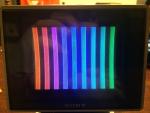
I don't have a lot of sets this old, so I'm not super familiar with the H sweep setup on this thing, and I don't know if the uneven brightness is my fault for setting it up wrong, or it's just due to aging components. If it's my fault, then that's down to the fact that there is a static horizontal convergence grid inside the tube, and I don't really know what to do with it. The Sam's say there should be either an HSTAT control OR Hor static convergence rings, but I think my set has both of them, based on the number of rings, and what those rings do. I have Purity plus two sets of rings besides, and all four sets effect convergence differently. Basically, when I did it, I tried to keep the HSTAT knob as central as possible, and adjusted for the best convergence and geometry, etc. All in all, it looks pretty damn good outside of the uneven raster. But could this be due to overcompensating in one direction or the other with the rings or the HSTAT control? The other thought I had was that maybe something in the geometry controls is throwing it off, because the H yoke ends terminate in the geometry circuit on one side and the convergence circuit on the other side. I would estimate based on that the H sweep is tied to those components, and any imbalance in the two sides of the H yoke could manifest as an uneven scan. You can see below in my picture where the two ends of the H yoke terminate. It's very different from what I'm used to. I don't even see something like an S correction cap. 

|
|
#3
11-06-2025, 10:58 PM
|
||||
|
||||
|
Quote:
I replaced C524 already. I went through and checked all the lytics on this set a couple years ago, and everything in the H/V sections was way out and got replaced. Taking it out and looking at it, I notice that the value is different from the service manual. Manual calls out 4.7, and I have a 10 in there. Chances are I wouldn't do that unless a 10 came out of the board though. I tend to go with the PCB over literature. But I guess someone else could have put it in there before I came around. I can confirm that swapping C524 out for a brand new 4.7uf cap did absolutely nothing. Also tested to see if the HSTAT or purity rings had any effect and they do not. I was going to test the other rings, but I doubt they will have any effect, and I'm getting tired. Can get back to it tomorrow. Last edited by vol.2; 11-06-2025 at 11:55 PM.
|
|
#4
11-07-2025, 05:49 AM
|
|||
|
|||
|
Very intringing. If the video output PSU cap are not the culprit as you already checked, I can assume that the bright only will change with:
Bad linearity, compressing the sweep in one direction, but then the image will be distorted; Some cap for the video coupling or decoupling in the video processing circuits?
__________________
So many projects, so little time...
|
|
#5
11-07-2025, 11:40 AM
|
||||
|
||||
|
Quote:
I'm mostly worried that the voltage multiplier is weak and it's not delivering even voltage across the sweep. Though I don't know if that wouldn't also effect the geometry? There doesn't appear to be any geometric distortion matching up with the brightness halo.
|
| Audiokarma |
|
#6
11-07-2025, 01:39 PM
|
|||
|
|||
|
Quote:
And is pretty rare to a CRT having a dim lateral zone (normally are the borders or, more rarely, in the center).
__________________
So many projects, so little time...
|
|
#7
11-10-2025, 12:16 PM
|
||||
|
||||
|
Okay. I think I finally figured it out. Hopefully.
The HOT is very weak. I realized that it's barely conducting, and I'm having to compensate for the screen width and geometry by pushing the controls all to one side. Testing it in circuit, the DC voltage of the HOT is 1.7V and it should be 108V. I didn't think that this could actually happen as I figured it would be completely dead if the HOT was so weak, but I guess this design it just acts as a boost or something rather than being the primary generation of the horizontal signal. It's weird that the geometry controls were actually capable of compensating for the size problem. Going to get a new one, but it's a weird old package. 2SC1034. Not sure how long it will take to find a good replacement.
|
|
#8
11-10-2025, 01:25 PM
|
||||
|
||||
|
Actually I didn’t think the second photo of the set looked too bad. Some of that bowing of the picture lines you have highlighted look like pincushion circuit issues. Might want to replace electrolytics in that circuit.
__________________
Sony Trinitron is my favorite brand. My wish list: Sony KV-7010U Sony KV-1220U
|
|
#9
11-11-2025, 12:39 PM
|
||||
|
||||
|
Quote:
In any case, I'm pretty sure I found the smoking gun. If you look at this portion of the schematic, I circled where I found a missing voltage on the collector of Q512. It's called the convergence output on the Sam's, but the SONY service manual calls it the HOT. It's supposed to have a 750Vpkpk signal on it, but it doesn't get anywhere near that high, and it's supposed to be 108VDC, but I only measure ~1.6V. There is about 114V present on the other side of that inductor. Amazingly, there's enough travel in the screen geometry controls to bring it up to about the correct size when the HV Size are at their full travel, but I think this is why the geometry is messed up, and also why there is an uneven brightness on the raster (because I have to use the HCENT to shift the screen all the way to one side). I found a transistor to replace it, but it will be some time before it comes in the mail. 
|
|
#10
11-12-2025, 08:01 AM
|
|||
|
|||
|
1.6V with the set on? Very strange. Or the DMM are playing havoc with superimposed waveform, or really it have something fishy in Denmark...
__________________
So many projects, so little time...
|
| Audiokarma |
|
#11
11-12-2025, 11:43 AM
|
||||
|
||||
|
Quote:
The fact that it isn't conducting would be creating other complex paths to ground for the 112V present on the other side of L508, because the failed transistor is not letting current flow through L508. Essentially, the current through L508 needs a path to ground to follow, but with Q512 dead, it can't reach the emitter of Q512, which is that path. That's the way I understand it, but I'm far from an expert. I think maybe Zeno could answer better, but I can promise that I'm not seeing any 108V on the collector of Q512. I have several multimeters, including an all analog one, and they are not seeing it. Measuring Q512 out of circuit reveals that it is *extremely* weak and the forward voltage is quite low on the collector junction specifically. I would guess that this is a fairly common occurrence, since the HOT is getting hammered on constantly during scan time. Last edited by vol.2; 11-12-2025 at 11:50 AM.
|
|
#12
11-27-2025, 10:05 AM
|
||||
|
||||
|
Replacing the damper diode didn't help the hourglass distortion, but it did increase my horizontal deflection signal by quite a bit. It was definitely weak. For some reason, this actually helped to make the picture look noticeably sharper, so that was worth doing.
I found what I think is the problem with the geometry now. There is a coil on the rear yoke assembly that the service manual calls "PIC". This is connected in parallel with another inductor and then in series with the main H Yoke. The PIC inductor is wrapped around a plastic ring and placed around the rear of the yoke. The other inductor is a little guy that is mounted next to the main front yoke. I found that the PIC inductor is low by about half. It's supposed to be 0.48 ohms, but it is about 0.22ohms (taken out of circuit). After looking at it carefully, I realized that it is stuck in place with the same brown glue as was on the rest of the PCBs and had gone conductive and corroded a lot of the capacitor legs and stuff. I got it off of everywhere else but here. Here is the yoke I'm talking about and the position in the circuit from the Sams. Does anyone have an idea how to remove the glue from this inductor without ruining it? I don't easily know how to replace it, and any original part would have the same brown glue on it.   I was able to remove the rear yoke assembly and at least remove the inductor wires from the glue where they join together at the terminal strip. This raised the resistance from a consistent 0.22ohms to a consistent 0.26ohms. The brown glue is all up and down both sides of the coils, so I am fairly confident that this is what happened with the spec of the coil. I don't know if this will actually improve the hourglass distortion, but the inductor appears to be labeled as something that controls the pincushion correction, so I'm hopeful. Last edited by vol.2; 11-27-2025 at 10:51 AM. Reason: Additional information
|
|
#13
11-28-2025, 07:54 AM
|
|||
|
|||
|
Anyway, this is really possible; a corrision. But the wires are so apart so is worth to check the oned that can cross like the ones that go to terminals. Or, the core is rather conductive and with corrosion... (but is easy to check)
__________________
So many projects, so little time...
|
|
#14
11-29-2025, 12:14 AM
|
||||
|
||||
|
Quote:
There was a fair amount of corrosion happening around the top of the coils, especially where they crossed the bottom side of the terminal strip. I scraped it all off and all the brown glue. Unfortunately, this didn't seem to be the problem. When I got the coils out and measured them, I found that each side was 0.48 ohms exactly, so I'm convinced that the Sams was giving the DC resistance per side and not the whole thing. This was with all the glue gone and no coils touch each other at all; this inductor is wound very loosely and doesn't overlap. So I don't know what to do now. Another symptom That I didn't think to mention is that when I change the horizontal size, the brightness of the raster changes. It gets darker when make it smaller. Pretty significantly darker actually. Now that I think about it, this seems fairly significant and wrong.
|
|
#15
11-29-2025, 12:58 PM
|
||||
|
||||
|
So I found that the boost voltage derived from the Horizontal Yoke pulses is quite a bit too high. In order to get the width to cover the whole screen, I end up with close to 600V boost, when I am supposed to be getting around 500-530V.
When I changed the width, it changes the boost voltage, and the boost voltage feeds the G2, which is why changing the width also changes the brightness. I don't really understand this. Is it by design? Should the loading on the boost rectifier determine its voltage? And if so, should it be this wide of a margin? You can see here where the boost is created. I assume it's rectifying the H yoke pulses as there is no other source I can see. 
|
| Audiokarma |
 |
|
|



 Hybrid Mode
