
|
|
|
#1
 10-21-2011, 03:56 PM
|
||||
|
||||
|
OK, Time for Many Admiral 30A1 Questions
Hi all,
This is my first post, so here goes.. I'm working on a 1948 Admiral 30A1 10" set. I've recapped the chassis and replaced a lot of bad resistors (some were tricky to disconnect to be tested, so I ended up replacing them, so the horizontal and vertical sections look "shotgunned"). I replaced a few weak tubes and after running the set for over an hour I rechecked the tubes and found a few more that were giving up. I get a picture and sound, and for the most part all the controls effect the picture or sound they way they are supposed to. However, I have a few bugs I've been working on. Some may be inherent to the design of the set, while others might be more a function of the video source (VCR and DVD player). I'll list the issues and see what you guys think (This is my first TV project, so bare with me!). 1. When I turn the Contrast dial, as the contrast decreases I noticed that the sound volume also fades. The Volume control is on the adjacent control, so it is not being caused by the outer dial dragging on the inner dial and turning it. 2. What is the proper distance that the focus coil should be from the deflector yoke? When trying to center the picture, I got the focus coil way out of whack as I didn't know at the time that the coil has to be angled opposite the way you want the picture to go. I backed it off to unload the tension springs so I could wiggle the coil by hand, and now even though I've tightened it back up, when I adjust the ion trap for the brightest picture the lower right corner of the raster is rounded off. It looks like I need to move the coil back in, but I wondered if there is a specified distance. 3. The raster has way too much width and the horizontal linearity is off. When the width adjustment coil is backed all the way out, you can just see the right-hand edge of the raster. If you screw it in at all, the right-hand edge also moves off the screen. Also, the horizontal linearity coil seems to have no effect on the picture. I went through all of the HV section, cleaning contacts and checking resistors to look for anything amiss. The Ryder manual mentions that "Tube aging (Which tubes?) may make horizontal linearity adjustment impossible" and that you can change the tap on the damping resistor to potentially remedy this. Interestingly, when powering up the set with a variac, you can see both the left- and right-hand sides of the raster until you get up to almost 90VAC, and then the left side moves off the CRT scren as the raster grows. 4. In many instances, there are thin diagonal white lines that cross over the picture. Are these retrace lines? I remember a thread here where someone mentioned that with Admirals of this vintage this may be normal. What gets me is sometimes they really stick out, other times you don't see them... Anyway, this ought to be plenty to get started with. Thanks! 
|
|
#2
10-21-2011, 07:02 PM
|
||||
|
||||
|
Most focus coils can not only be moved back and fourth, but also tilted to keep good focus and eliminate corner shadows.
If the Retrace lines consist of dashes come and go in the top to the screen and they don't run the full distance from side to side that it is porbably the copy protection signal from the tape or DVD that you are seeing. You can buy devices that will remove the offending copy protect signal if you want. I'm not familiar with early admirals, but can offer that some vintage sets of some brands pick off the audio signal after the contrast control and may have their sound affected by it. Hope this helps.
__________________
Tom C. Zenith: The quality stays in EVEN after the name falls off! What I want. --> http://www.videokarma.org/showpost.p...62&postcount=4
|
|
#3
10-21-2011, 07:06 PM
|
||||
|
||||
|
Hi, and welcome to VK. This group includes some real Admiral junkies-- er, experts, so I'll let them answer the hard questions.
Re Question #4, the slanty retrace lines, they are common to many 1940s TVs that lack vertical blanking circuitry. If you're not interested in modifying your set, the remedy is turn down the contrast until they just disappear. I haven't tackled any Admirals yet, although I have a similar model waiting in the garage until its turn comes up. You can see a photo in this thread. Maybe this winter . . . . Phil Nelson
|
|
#4
10-21-2011, 07:09 PM
|
||||
|
||||
|
On early Admirals, the contrast control really is a signal strength control, a potentiometer on the front end circuits. I had one that would do the same thing as you turned the contrast down, until you had no signal, only snow. Turning the control up all the way produced overloaded video and blasting sound.
Depending on your video source, you may be viewing copyguard lines on your video, especially if they fade in and out periodically.
|
|
#5
10-21-2011, 07:33 PM
|
||||
|
||||
|
Yes, in my service manual for 1952 Admiral 21F1 chassis explains that the contrast control is an additonal gain level with the varying level fed into the video tubes.
|
| Audiokarma |
|
#6
10-21-2011, 07:35 PM
|
||||
|
||||
|
Quote:
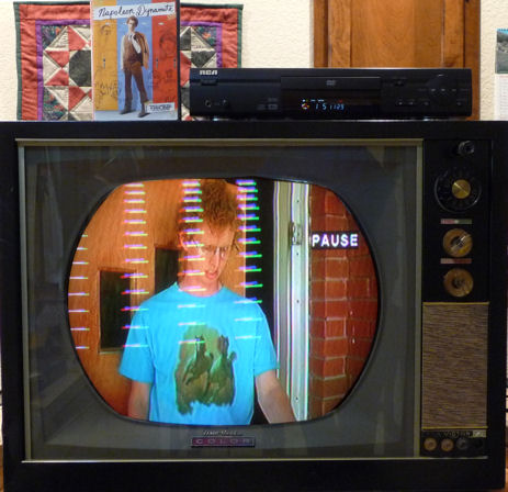
 You can see the little dashes at the top. The diagonal lines can be made to jitter with the Vertical Hold adjuster. Even when you turn the Contrast all the way down, those lines are still there, just superimposed on a gray screen.
|
|
#7
10-21-2011, 07:45 PM
|
||||
|
||||
|
...the copy-protection is quite visible during retrace/vertical blanking on all my sets when you look at the scope, but is only visible 'on screen' on some of them. (btw, is this Macrovision on dvd or something else.)
I think a lot depends on the set's video output circuitry, many old tv's tend to blank this out along with the rest in the VBI but others have obnoxious lines at the top.
|
|
#8
10-21-2011, 09:39 PM
|
||||
|
||||
|
I'm a self admiitted Admiral junkie :P
1. As stated above the contrast affects the gain / AGC, so what you observe is normal. 2. About 1/2". Here's a photo of a freshly pulled chassis with tape measure. Also be sure your yoke is snuggly against the CRT bell and that the dual ion trap magnet is on the right way. The blue section goes towards the CRT face.  3. Could be related to #2. Also, have you adjusted the Hor. Lock and Hor. Drive as described in the service info ? 4. Yes, these early Admiral do have prominent retrace lines, but they are excessive in your photo I think. You should be able to adjust the brightness and contrast and get a picture like this taken from a similar Admiral set. What are you using for a video source ? I'm using an over the air DTV receiver through a 75-300 ohm balun to the antenna terminals. 
Last edited by bandersen; 10-21-2011 at 09:43 PM.
|
|
#9
10-21-2011, 09:41 PM
|
||||
|
||||
|
The lowest 6-9 dashes are macrovision (I coulden't remember the name earlier and called it copy protection) and they occur on the fainter slanted retrace lines. The macrovision has to be filtered out of your signal source with an external device of your choice (there are many avaliable). The retrace lines can be made unnoticable by either adjusting the brightness and or contrast to make them disapear, or by adding a blanking circuit (some tube sets have blanking circuits built in so it may be that the circuit is not working right if it is present).
__________________
Tom C. Zenith: The quality stays in EVEN after the name falls off! What I want. --> http://www.videokarma.org/showpost.p...62&postcount=4
|
|
#10
10-21-2011, 11:39 PM
|
||||
|
||||
|
Howdy, and welcome.
I added the below blanking circuit to my 20A1 chassis about 15 years ago. Only one capacitor and a resistor, it really works well on my set. This is right out of Milton S. Kiver's-Television and F-M Receiver Servicing (great book by the way). The circuit shown is almost identical to your set. Hopefully you can see it well enough here, otherwise pm me and I can email a full size scan.
|
| Audiokarma |
|
#11
10-22-2011, 12:30 AM
|
||||
|
||||
|
Columns of dashed lines that extend down into the picture are definitely copy protection. Here's a wicked case, shown on my 1961 CTC-11.
 Google for "video stabilizer" to find inexpensive devices that will let you play your copy-protected DVDs on your old TVs without this annoying hash. Different TVs respond differently to this stuff, and I imagine there are different copy protection schemes. In any case, the stabilizer lets me play any of my DVDs on any of my old TVs. This is different than the other two hash sources mentioned (the thin horizontal row of dashed junk at the extreme top, and the widely spaced diagonal lines). Phil Nelson Phil's Old Radios http://antiqueradio.org/index.html
|
|
#12
10-22-2011, 08:17 AM
|
||||
|
||||
|
Quote:
As an aside, I've heard quite a few interesting stories about the guy who used to service this TV for my grandparents. My mom recalled that when he would come over, that supposedly was the only time my grandmother would make fudge...  My uncle also remembered when he bought his first Hi-Fi setup. George (our repairman) came by to look at it and clipped out a few parts, telling my uncle, "There. That will sound much better. Those parts are more for wattage than fidelity." Sure enough, the set was still plenty loud, but the sound was more true. My uncle also remembered when he bought his first Hi-Fi setup. George (our repairman) came by to look at it and clipped out a few parts, telling my uncle, "There. That will sound much better. Those parts are more for wattage than fidelity." Sure enough, the set was still plenty loud, but the sound was more true.
|
|
#13
10-22-2011, 09:55 AM
|
||||
|
||||
|
Quote:
First is the copy protection that has been mentioned. The other problem is retrace showing. Before you do the mentioned added capacitor, check the grid coupling capacitors on your video output tube for leakage. Check either by substitution with a known capacitor, or with a battery (at least 15 volts, better higher) in series with the suspected capacitor. The voltmeter reading should drop to zero in a few seconds if the cap is good. Bad ones go to almost zero, but never to zero. It usually is not the first video, but it does no harm to check that one the same way while doing the other. James
|
|
#14
10-22-2011, 10:41 AM
|
||||
|
||||
|
I messed around with adding retrace blanking to my Admiral 20B1, the thread talking about it is here: http://www.videokarma.org/showthread...hlight=admiral
|
|
#15
10-22-2011, 05:25 PM
|
||||
|
||||
|
All the capacitors in the set are new.
It seems that #1 is OK, and is to be expected. That's fine, as if it is normal I'm OK with it. I just wanted to make sure I didn't mis-connect something. I was given a DTV converter and today I picked up an amplified antenna as well as an RF interference trap. I wanted to compare "broadcast" TV vs DVD and VCR signals. My setup is as follows: I have the antenna hooked up to the DTV converter via coaxial cable, which is then connected to the "IN" on the VCR. The DVD is connected to the VCR so the VCR acts as the RF modulator. The VCR is connected via coax to the RF interference trap, and then to a 75 ohm coaxial to 300 ohm dipole converter. I also temporarily reconnected the removed circuitry to see how it effected the retrace lines. The retrace lines still show up no matter the video source, but the added circuit seemed to diminish them. I can live with them for now, knowing they are normal for an Admiral set, and I am able to tune them out most of the way. The big issue I need to address now is the excessive width of the raster. The height I can adjust with no problems, and I have the picture somewhat better centered on the screen. It extends approximately a half-inch beyond the widest point of the CRT. The tube mask is only about 8" wide, so when the chassis is installed in the cabinet a lot of the picture is chopped off. I have a feeling if I can get the width down to the correct level, the linearity control will have a better effect. Last edited by UberVacTuber; 10-22-2011 at 05:40 PM.
|
| Audiokarma |
 |
|
|


 Linear Mode

