
|
|
|
#29
 01-31-2017, 12:03 AM
|
||||
|
||||
|
Flickr huh, i'll give it a try later.
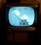
Guy's,... Suggestions??? Well, I changed out some bad resistors and got no change in operation, that I noticed. Probably more to go. Anybody got a better copy of the schematic? The Sams i'm using from ETF is very blurry in some spots. For example, Looking at my print out compared to it on my pc, I got a wirewound resistor (R90) i'm confused about. On paper it looks like it's 2.5ohm, but on my pc with it zoomed in, it could be 7.5??? Since the one in place was real high, I put a 4ohm wirewound in that I happened to have on hand. I could also use more voltage diagrams on some of the lines. For example, on C1. The original part is a 140mfd/150v cap. I measured it and voltage fluctuates from 148-151. That seems a little high to me, as I would figure manufacturer's wouldn't want to push there components that close to there maximum's. Question about that part too. If C1 was bad, would that contribute/cause my pictures' wave? The new cap is a 150MFD/450V unit, and it actually gets warm?! With a voltage rating so much higher than nessisary, I wouldn't think it'd get warm. 
|
|
|




 Threaded Mode