Videokarma.org

Go Back   Videokarma.org TV - Video - Vintage Television & Radio Forums > Diagnostic & Test Equipment

Notices

We appreciate your help

in keeping this site going.
 
 
Thread Tools Display Modes
Prev Previous Post   Next Post Next
  #11  
Old 05-12-2017, 10:43 AM
Kevin Kuehn's Avatar
Kevin Kuehn Kevin Kuehn is offline
Workin' Late Again
 
Join Date: Jan 2011
Location: WI
Posts: 3,976
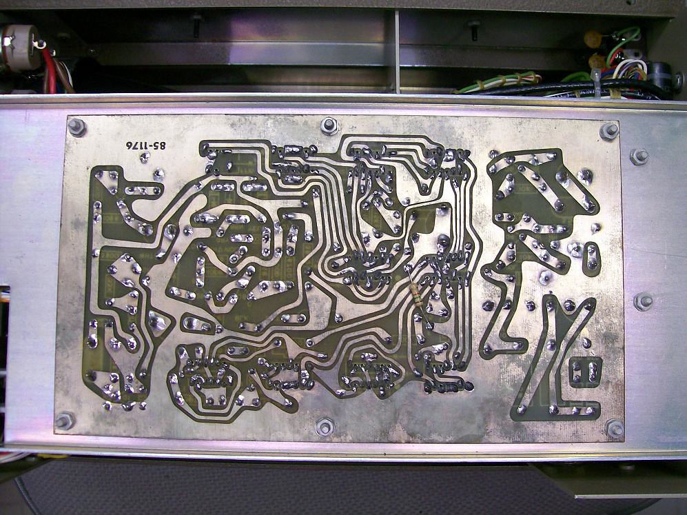
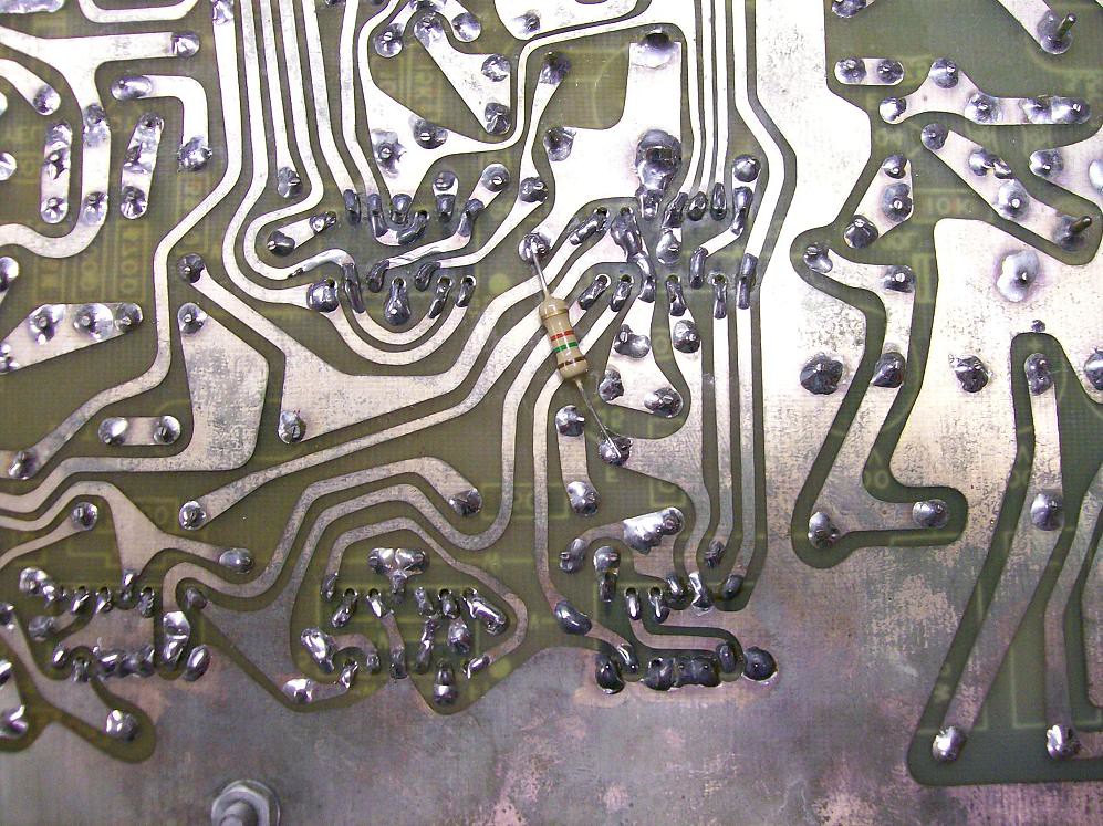
Here's a couple pictures of where I located the 1.5K on the back side of the circuit board. It's between pin 4(ground) and pin 10(input to G1 gate which is IC 9 in the manual). You will need to adjust the Vertical Blanking Width pot(R35) in order to get the best line pattern at the top of the picture. Basically you will be adjusting the width of the vertical blanking pulse, which determines where at the top of the screen the horizontal scan begins. When that pulse is too wide you see the vertical blanking pulse turn off transistion, which is what causes the wiggle in the vertical lines. Hope that makes sense. Let us know how it works out.


Last edited by Kevin Kuehn; 10-21-2017 at 09:00 PM.
Reply With Quote


Posting Rules
You may not post new threads
You may not post replies
You may not post attachments
You may not edit your posts

BB code is On
Smilies are On
[IMG] code is On
HTML code is Off

Forum Jump


All times are GMT -5. The time now is 07:25 PM.


Powered by vBulletin® Version 3.8.4
Copyright ©2000 - 2026, Jelsoft Enterprises Ltd.
©Copyright 2012 VideoKarma.org, All rights reserved.