
|
|
|
|
|
#1
 01-27-2007, 01:55 PM
|
||||
|
||||
|
Basically your understanding is correct. What is essentially being done is increasing the verticle height adjustment.
Actually the lines stay the same thickness, but the space between the lines gets wider. The thickness of the line is determined by the diameter of the electron beam from the gun, and the divergence of the beam which is related to the distance from the gun to the screen. As for the Yoke issue. We are talking about only increasing the height about 1 inch on top and 1 inch on bottom. So an increase in voltage causes a stronger magnetic field and thus a stronger deflection upward and downward. I am not sure if the Yoke has any special charastics over a yoke in a conventional set. My guess is that it's nothing special. If there is any relationship in the length of the tube and timing it would be so small as to not be significent. Electrons travel at the speed of light. Verticle oscilator frequency does not vary. It must stay at 30 frames per second to sync with the broadcast from the network. What varies is not the duration of the ramp waveform that drives the verticle section, but rather the peak positive and negative values of the voltage comming out of the verticle output transformer, (which is driven by the verticle output amplifier tube) which drives the verticle coils of the yoke. A simple analogy would be when you turn up the volume of your stereo, you don't change the waveforms of the sound or the durations of those waveforms. You only change the verticle amplitude of the waveforms and thus the loudness of the sound. The verticle output section of the tv set is very much like a vacuum tube audio amplifier. A ramp waveform (the input signal) drives an output tube which in turn drives an output transformer (to obtain an AC positive and negative voltage) which drives the verticle coils of the deflection yoke (just like you drive the voice coil of a speaker to make it move forward and backwards). Look at it this way. The verticle voltage driving the verticle coils of the deflection yoke is driven by a sawtooth ramp waveform. When the ramp voltage is at it's positive peak, the verticle voltage at the yoke is at it's max and the electron beam scans the top most line of the picture. When the ramp wave drops and crosses the zero axis, the voltage at the yoke is zero and the electron beam scans across the middle of the tube. When the ramp wave reaches the bottom of the cycle it is at the most negative value and the voltage at the Yoke is at it's most negative value and the scan line is at the bottom line of the picture. By varying the peek voltage of the ramp waveform comming out of the verticle amplifier tube, you vary the maximum positive and negative voltages applied to the yoke via the verticle output transformer. The the verticle waveform driving the verticle output amplifier tube, is a ramp because at the end of each frame of the picture, the voltage needs to instantaneously return to the beginning of the cycle and start scanning a new frame at the top of the picture with virtually no time delay. As the value of the voltage on the ramp waveform drops from highest to lowest value, the electron beam scan lines move from the top to the bottom of the screen in a corresponding fashion. Hope I haven't confused you too much, but basically you had the right idea.
__________________
Vacuum tubes are used in Wisconsin to help heat your house. New Web Site under developement ME http://AntiqueTvGuy.com 
|
|
#2
01-27-2007, 04:13 PM
|
||||
|
||||
|
Electronic magnification
There were several late 1940s TVs which featured some form of magnification or zoom. Most designs simply increased the vertical height, as discussed earlier in this thread.
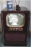
But Westinghouse took the concept to its logical extreme in the Model H-605T12. This 12 inch table set has a front panel control labeled electronic magnification. When in the normal position, the CRT was masked off in the conventional "double D" format; that is a round CRT with the top and bottom masked off and the sides left rounded, to approximate the 4:3 aspect ration of the trnasmitted image. When the control was moved to the magnification position, two things happened. First, two mechanical shutters at the top and bottom of the CRT moved outware to reveal the full round CRT. Second, both the vertical sweep height and horizontal sweep width were increased to completely fill the round CRT, while maintaining the 4:3 aspect ration of the inage. The magnification was accomplished by switching in two separate vertical height controls to set the vertical height, and the B+ voltage to the horizontal output stage was switched between 2 values to cause the width to change. In a conventional flyback type horizontal deflection system, changing the B+ voltage would have drematic effects on the high voltage as well as the width. Westinghouse avoided this complication by implementing a RF type high voltage power supply, which operates independently of the horizontal deflection circuitry. This HV supply is a souped-up version of the RF high voltage supply commonly used in 7" sets of the period. It was relatively uncommon to use RF high voltage supplies in sets employing CRTs bigger than 7 inches. The horizontal deflection circuitry of this set used 3 7A3's in parallel to drive a conventional transformer coupled deflection yoke. This set can be found in Sams #97-19.
__________________
John Folsom
|
|
#3
01-27-2007, 04:59 PM
|
||||
|
||||
|
WOW John,
I just acquired a Westy like the one in the photograph. I did not do anything to it yet except test the crt. I had no idea that there was a shutter attached to the magnification control or any of the other very interesting features of this set you mentioned. I will have to look more closely at it as soon as I have a chance. I already have the Sams for it. The cabinette is in pretty bad condition but I think it can be restored. Chassis looks unmolested from what I can see. Thanks for this most interesting information ont he Westy.
__________________
Vacuum tubes are used in Wisconsin to help heat your house. New Web Site under developement ME http://AntiqueTvGuy.com
|
|
#4
02-27-2008, 04:02 PM
|
||||
|
||||
|
Quote:
LJB 
|
 |
| Thread Tools | |
| Display Modes | |
|
|







 Hybrid Mode
