
|
|
|
|
|
#2
 01-19-2008, 12:08 AM
|
||||
|
||||
|
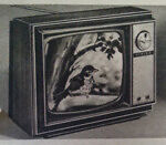
I've got a 10T1 that I just fixed up after many months of slow troubleshooting and repair.
Your controls out back starting from the left horizontal frequency- Horizontal drive, Thermal cutout switch - focus range adjustment(use in conjunction with the front focus control) Vertical height, and vertical linerarity. My set uses the bakelite locomotive cabinet, which arrived shattered from UPS. I didn't bother with a claim, as they would blame it on the seller packing bad. I was quoted 160 for a restorationist to repair the cabinit. I found bad resistors in the set in the sync and vertical sections. Also there was a cap that connects to the sync tube that looks like a huge white resistor with a color code. I neglected to replace it because I thought it was a resistor. Replaced it and my contrast control began to work. These sets I don't think were top of the line performers. The contrast control mearly adjusts the gain of the IF tubes. Also the tuner is a turret type that really needed to be cleaned. Oh, and I had to replace the video detector diode, that was hidden in a IF transformer can on top of the chassis. I used a common switching diode from radio shack. Before replaceing that I had no audio or video. Post your progess, I am interested to see how your restoration goes compared to mine. Good luck, Matt Davala 
|
|
#3
01-19-2008, 05:20 AM
|
||||
|
||||
|
I haven't had much of a chance to work on it these days , I still have to dig in there and list all the electrolytics , and get a order together for the caps .
My 1954 Crosley also has a detector diode in it , hiding under a IF transformer , 1N34 or equivalant . I still have to get a schematic for it . They have a neat circuit layout , with the 2 boards , and all the parts are fitted to those . they are quite a neat little set I like the brass front . They were not a really expensive set I would imagine , considering they were series wired tube filaments I got the chassis sraightened out , just a few little spots left to fix . What it the thermal cutout switch for ?
|
|
#4
01-19-2008, 10:32 AM
|
||||
|
||||
|
Well from what I can tell about the thermal cutout is that its first job limits the initial current rush. It takes the set longer to turn on, but protects the tubes filiments from that initial "flash" that most series strung sets have.
The second job is to act like a circuit breaker in the event of a short in the B+ it will open the thermal cutout. I was just reading your first post and saw that one of the 12AT7's had an open heater. Same with my set. I had a spare Groove Tube 12AT7 that works just fine. The set had all origional GE 6AG5's that tested weak to marginal. If you read the service notes for the set, after 1950 replace ALL 6AG5's with the "new" 6BC5. AES had NOS 6BC5's for 1.50. I ordered 5 from them and one tested weak. I called and they were super nice and sent me out another 6BC5 no questions asked. Best Regards, Matt Davala
|
|
#5
01-19-2008, 11:45 AM
|
||||
|
||||
|
Actually, the Thermal switch is only in case of shorts. The two special resistors in the hv cage are for surge. Of filaments, that is..
Yes, these sets take forever to warm up... About two minuites, and, I'm not real impressed with the picture quality, either.... Actually, they didn't use a turret tuner. They used their own style of wafer tuner.... Bill Cahill
__________________
"Tubes are those little glass things that light up orange unless there is a short.. Then they light up all pretty colors..." Please join my forum. http://www.tuberadioforum.com/
|
| Audiokarma |
 |
| Thread Tools | |
| Display Modes | |
|
|







 Hybrid Mode
