
|
|
|
#1
 01-02-2008, 06:56 PM
|
|||
|
|||
|
radio repair in Montreal?
Heya,
I frequently pick up vintage turn tables and radios and tinker with them until I manage to get them up and running... but I am having zero luck with a recently acquired radio. The model number says 7ET72-E. I am looking to hire someone to repair the actual radio. Anyone know of a place or person I could contact around Montreal for help? cheers! Michael 
|
|
#2
01-02-2008, 09:11 PM
|
||||
|
||||
|
Quote:
Can you make out the manufacturer's name? and how about posting some pics. Who knows, the problem could be simple, something you could do yourself...
__________________
Experience is what you get when you don't get what you wanted.
|
|
#3
01-02-2008, 09:26 PM
|
||||
|
||||
|
Hi Michael,
I am in Montreal too, I would be glad to help you. But as Aage just told you, more info is needed. Is this a 10-, 25-, 45- or 60-year old radio? The old radio hobby, like every hobby when you get to think of it, is best enjoyed once you learn to do most or all the work yourself. Good luck and keep us posted, you're on the right forum!
|
|
#4
01-02-2008, 10:06 PM
|
|||
|
|||
|
Thanks for replying guys,
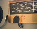
I just took a couple of photos of it. I've obviously taken it apart, redone the exterior completely, but am including a photo all the same. The other photos are of the actual radio, and the labels accompanying it. Any thoughts or suggestions? http://img.photobucket.com/albums/v3.../radio008a.jpg http://img.photobucket.com/albums/v3.../radio005a.jpg http://img.photobucket.com/albums/v3.../radio006a.jpg http://img.photobucket.com/albums/v3.../radio010a.jpg http://img.photobucket.com/albums/v3.../radio009a.jpg http://img.photobucket.com/albums/v3.../radio004a.jpg
|
|
#5
01-03-2008, 12:41 PM
|
||||
|
||||
|
Hello again,
These pictures do tell a lot. Your radio is a Viking unit, marketed by Eaton's of Canada. The chassis uses a combination of pre-octal tubes (80, 42, 76, 6A7, 6E5) and octal-base metal tubes (6K7, 6F5, introduced in 1936). It would appear from this combination that this radio was manufactured around 1936-1938. The 6A7 is one of the earliest pentagrid converter tubes, making it possible to achieve frequency conversion (or first detection as it was sometimes called) with a single tube. Another interesting feature of this radio is that is does not include any actual detector diode in its tube lineup. Detection is probably achieved usind the 6F5 wired as diode or an infinite impedance detector. A schematic would help. It is most likely that your radio uses an electrodynamic speaker, meaning that the constant magnetic field is provided by an electromagnet rather than a permanent magnet. The electromagnet coil also acts as a filter choke for the power supply. There are two important facts in relation with this: 1 - High voltage is present at the loudspeaker wiring, so be careful with broken wires, frayed insulation, etc. 2 - The radio won't work at all (except for the tube heaters lighting up) if the field coil is open or disconnected. This is a nice radio, and the chassis appears to be in good cosmetic condition. I believe it is worthy of a good restoration. It would help very much at this point if you would let us know what you attempted to do and what happened. Bye for now.
|
| Audiokarma |
|
#6
01-04-2008, 07:03 PM
|
||||
|
||||
|
Hello again micsmeets,
Hope I did not scare you with all this technical stuff... Please get back whenever you feel like it, I sincerely look forward to helping you. Bye for now. Last edited by electroking; 01-07-2008 at 01:15 PM. Reason: to correct a typo
|
|
#7
01-09-2008, 12:14 AM
|
|||
|
|||
|
Nope, not scared... just been a very busy week at the bar, and haven't had much time to go online.
I'm also leaving this morning for my vacation, and will be back on the forum when I return, the 19th. Thanks for the help, and talk to you soon! Michael
|
|
#8
01-24-2008, 02:52 AM
|
|||
|
|||
|
Sorry for being gone so long, but vacation being vacation, there was a shit-load of work waiting for me when I returned.
Anyhow, I did very little with this one when I got it. Simply replaced a couple of tubes which were very obviously damaged. Apart from that, nada.
|
|
#9
01-24-2008, 05:35 AM
|
||||
|
||||
|
Typically, on a 70-yr-old set like this, a re-capping job is in order. Once you do get it all squared away, this set should give you lots of pleasure for a long time, though.
__________________
Benevolent Despot
|
|
#10
01-24-2008, 02:52 PM
|
||||
|
||||
|
Hello again micsmeets,
Good to see you back, hope the vacation was up to your expectations! In case you need an explanation, a re-capping job means replacing some capacitors, namely the electrolytic and waxed paper ones. There are at least two electrolytic capacitors in this chassis. One of them is the big metal can standing between the 76 and 42 tubes, and the other looks the same. Modern replacements will be much smaller. As a first step, they can be installed under the chassis, and later on the cans of the original capacitors may be emptied, and the replacement units mounted inside. If a schematic is not available, two capacitors with 40-microfarad capacitance and a voltage rating of 450 volts should work fine. Electrolytic capacitor are polarized, meaning that they have a + and a - terminal. It is most likely that the - terminal goes to chassis ground. There might be one more electrolytic capacitor used as a cathode bypass on an audio stage, but this is unlikely in an old radio like this. It is important to avoid powering up the radio until the condition of the field coil is checked, otherwise the electrolytic capacitors and rectifier tube (80) could be damaged. The waxed paper capacitors (or simply paper capacitors) are fairly big cylinders (somewhere between a half- and one-inch in diameter, and maybe 1 to 2-inch long). There may be a dozen or so in your radio. All should be replaced with modern unit with the same capacitance. Voltage rating of the replacements is unimportant as long as it is at least as high as the original. Many of the values might be impossible to read, which once again makes it desirable to get a schematic. The following link is typical of companies that can provide the required info: http://www.justradios.com/schematics.html If you would like to meet me, talk to me or get me to have a look at the radio, just send me a message and we can arrange something. Best regards. P.S.: if you would let us know a little better the kind of test equipment you have, your experience with troubleshooting and soldering, etc., that would allow us to help you better. Last edited by electroking; 01-24-2008 at 02:53 PM. Reason: to correct a tube number
|
| Audiokarma |
 |
| Thread Tools | |
| Display Modes | |
|
|







 Linear Mode

