
|
|
|
#1
 04-13-2008, 05:09 AM
|
|||
|
|||
|
Latest Find. Kriesler Hi-Fi Console TV
This TV is an Australian set manufactured in late 1965 or 1966. They were Krieslers top of the range set and could be considered state of the art for the period.
The TV comes with a cabled remote for volume / channel selection etc and the tuner is motor operated. The chassis fitted to this set is known as the "SuperF" chassis for fringe reception as well as town use. It features selectable (internal) adjacent channel traps, 3 vision IF stages, separate vision and sound detectors, noise reduction circuits and CRT brightness regulation. Other features of this set are the clock which can be set to turn the set on and off by itself and switchable 4 speaker Hi-Fi sound. The set is currently non operational as the person I acquired it off attempted to power it up after saving it from a deceased estate. The result is one vertical stage filter electrolytic that blew out. The resulting electrolyte spray is just visable below the CRT neck. Repairs etc will occur later in the year as I have other TV's that need doing first. The TV also came with a matching radio/gram featuring the same speaker system and approx 8 watts per channel (stereo). It has survived the shock test treatment and is said to work well. I will confirm the chassis condition for myself before trying power on it again though. 
|
|
#2
04-13-2008, 05:38 AM
|
||||
|
||||
|
Doncha just LOVE IT when they try to "Fire 'er Up" ?....Sometimes literally...And these self-appointed "experts" always say, "Aww, hit's jus' a Tube went bad.. you can get anudder one easy enuff.."...Grrrr....
__________________
Benevolent Despot
|
|
#3
04-15-2008, 02:19 AM
|
|||
|
|||
|
Indeed, I'm glad that no serious damage occurred. The blown cap is current limited by a 330 ohm resistor which was probably very unhappy about its unexpected new load.
I forgot to mention that the TV and Radio/Gram use electrostatic tweeters. I've checked the circuit to make sure they use HT bias and they do. It will be interesting to hear what they sound like.
|
|
#4
04-15-2008, 03:15 AM
|
||||
|
||||
|
Kriesler BW TV
Congratulations, Andrew, a nice find. I had one identical at one stage, until I had to give it back...
I have a "Multi-Sonic TV Theatre" which I rebuilt some years ago, and after the CRT and HT were replace, plus all the usual caps, it's functioning perfectly. Please see the attached photo with the TV on it's usual Sunday morning run. Good luck with the resto - as you say, Kriesler was top of the range in its day. PS How is the Devon Fringe going? Last edited by Alan Merritt; 04-15-2008 at 03:18 AM. Reason: no picture..
|
|
#5
04-15-2008, 03:24 AM
|
||||
|
||||
|
Here's the picture
Third time lucky!
|
| Audiokarma |
|
#7
04-15-2008, 07:36 PM
|
||||
|
||||
|
Quote:
That TV is sooooo cooool!
__________________
From Captain Video, 1/4/2007 "It seems that Italian people are very prone to preserve antique stuff."
|
|
#8
04-16-2008, 05:02 AM
|
|||
|
|||
|
Some more info for the curious.
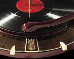
The TV uses the 79-17 chassis. This should be a fairly quick set to recap as the majority of the capacitors are Philips "mustard" polyesters which have a good reputation for reliability. A quick look at the chassis underside revealed a total of five wax capacitors mostly around the horizontal sweep power section. There are a number of suspect electrolytics but the main filter cans look good externally. I'll have a try at reforming them. The radiogram uses the 11-97 chassis which has a valve tuning indicator and a pair of 6GW8 triode pentodes as output valves. The turntable is a Garrard AT6. Some quick research reveals that this was a respectable turntable in its day. Alan, I like your set but it does take up some room! I'm glad mine is in two parts, it's much easier to handle. What radiogram chassis does yours use? The Astor Devon you asked after actually belongs to another Victorian AK'er Dr.Ido. As requested, here are some pictures of the radiogram section. The top view picture also has the TV remote and microphone for the radiogram in it. I'm very happy that these are still with the set. The last picture is of the radiogram chassis. A very good design idea this. The top half hinges up after undoing two screws for excellent service access.
|
|
#9
04-17-2008, 06:16 AM
|
||||
|
||||
|
Kriesler 3-in-1 Model RA-98
Andrew - the TV is a 79-17, and the stereo a split chassis model, with 89-30 for the power supply/power amplifier & 89-31 for the radio and preamplifier.It has two 8" twincone speakers and two 9x6" speakers.
It is very big, and immensly heavy, but as I now own the house I live in, it should be able to stay put! Five moves of it has, I think, resulted in my spine being slightly compressed... My first Kriesler stereo resto was a blonde wood unit identical to yours, and it now graces the living room of my brother, across the room from his Kriesler colour TV 660-18, which I've managed to keep operating well. I have a later model stereo in darker wood, an 11-97 with four 6GW8s and electrostatic speakers. It has the video and TV sound routed through it, and a lovely warm tone with lots of volume. I'm currently working on a very early Kriesler TV model 79-2 dated June 1959, so not only is it more ancient than me, but one of SA's first TVs. I've replaced all the big rating capacitors, as well as the two 6N3 rectifiers, but still the picture is very small and fades eventually. Any hints? The picture gives a bit of an idea.
|
|
#10
04-18-2008, 02:49 AM
|
|||
|
|||
|
Do you have the schematic for your 79-2? If not I can help you out with one.
I have a few ideas with your problem. As you have normal horizontal scan, the fault must lie in the vertical stage or its power supply. Looking at the circuit for it, the V output stage has its own dedicated 205 volt supply derived from the main rectifier HT via a 1k resistor. Make sure this supply is ok. The next area to check is the circuit associated with the vertical height control. It uses the boost HT supply (700-750 v) via a potential divider of high resistance to supply the vertical oscillator circuit. These high value resistors are prone to drifting high in value which would reduce the height. You say you have replaced the big rating capacitors. Does this include the waxed paper capacitors? There are some prime candidates in the circuit that if leaky would produce the same problem.
|
| Audiokarma |
|
#11
04-18-2008, 12:53 PM
|
||||
|
||||
|
What an interesting set. It's fun to see something different.
Regarding the electrolytics, I would replace them. You can't tell their condition from appearance. I have not had good luck with reforming old electrolytics -- they may work for a while, but not for long. Replace the paper caps, too. Congratulations on your find. Phil Nelson
|
 |
| Thread Tools | |
| Display Modes | |
|
|





 Linear Mode

