
|
|
|
|
|
#1
 01-23-2009, 11:31 AM
|
||||
|
||||
|
Those coils take a pretty small screwdriver; they can be tough to find, and even tougher to keep the driver in the slot while you are making adjustments. There are wires that sometimes poke up and get in the way, too, so you may have to push them out of the way.
__________________
Bryan 
|
|
#2
01-23-2009, 04:53 PM
|
||||
|
||||
|
You're Getting There!
Wayne, seems the major part of the CTC5 restoration is completed, looking good! My Dad's CTC4 of 50yrs ago was my first adventure into color TV and was the first narrow-band chroma RCA made after the CT-100 based 21CT55. It used the same 21AXP22 but had at least 10 less tubes. I recall that the CTC5 was designed to eliminate some of the CTC4's worse problems but it remained narrow-band. Did RCA or any other tubed roundy maker return to the original NTSC wideband, low level chroma demodulators?
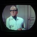
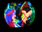
As you continue refining your CTC5's picture quality, please continue posting your screen shots in the highest resolution. I use DVD test disks to evaluate all my CTVs and compare their PQ against the highest performance modern ss CTV that can be accommodated in my tiny lab. My favorite DVDs are "Digital Video Essentials" and "Planet Earth". Obviously the goal is to get the TV being evaluated to produce the closest PQ to the "Lab-Standard" PQ and capture the comparisons with a quality digital camera in JPG format....Tom
|
|
#3
01-23-2009, 06:34 PM
|
||||
|
||||

I can't refer to the other "COLORTRACK 2000" receivers, but the CTC-133B (1985/86) is a wide
 band receiver, using IC's made by NEC of Japan, utilizing IQ demodulation. The CRT seems to produce better reds than some of RCA's previous models. I have a copy of this chassis, and it is a very good performer as far as color reproduction goes, but is does not produce what I would call a bright picture, perhaps due to the choice of more accurate phosphors at the expense of brightness. The only trouble I have had with it is a failed audio chip, and an open resistor on the CRT board, both easy repairs. band receiver, using IC's made by NEC of Japan, utilizing IQ demodulation. The CRT seems to produce better reds than some of RCA's previous models. I have a copy of this chassis, and it is a very good performer as far as color reproduction goes, but is does not produce what I would call a bright picture, perhaps due to the choice of more accurate phosphors at the expense of brightness. The only trouble I have had with it is a failed audio chip, and an open resistor on the CRT board, both easy repairs.I have a CTC-4, CTC-5N, and CTC-7. RCA specifies "X and Z" demodulation in the deluxe CTC-5N, and subsequent chassis, which is , I believe, narrow band demodulation, although with improved circuits over the model years. All can produce excellent color pictures, within the limitations of their design, as can the CTC-5 Special, as has been demonstrated on this forum. Kevin
__________________
stromberg6
|
|
#4
01-23-2009, 09:21 PM
|
||||
|
||||
|
Quote:
Demodulators that went directly to the CRT grids (like the (R-Y)/(G-Y) in the CTC-5 "Super chassis) were probably the narrowest because of needing high load resistance to get the necessary gain in a single stage. The X-Z were somewhere in between. They could not have too much bandwidth, or they would show bad color edges due to I/Q quadrature crosstalk; but they would not be so limited by the capacitive rolloff, due to having some gain in the demods and some in the matrix amplifiers. I am quite familiar with the 80's attempt at I/Q demodulation in the RCA solid state set, as I studied it closely while looking at the possibility for widebanding at Zenith. The fact is, creating an IF that passes the chroma without introducing phase distortion of the upper sideband can be quite difficult (although surface-wave IF filters could probably be designed to do it). Unfortunately, RCA did not succeed, and the high-frequency I channel gain on that set was so low in order to hide problems that it did little to improve the chroma resolution. It could fairly be said to be present in the set for advertising purposes, but that was about it. It's too bad, because some very clever design went into the analog color chip to minimize pin count while sitll providing the required I-channel delay line. It is one of my favorites. The designers came up with an amazingly clever way to drive and sense the delay line with a single pin! However, when we put the set side by side with an equiband Zenith (which had a very simple color takeoff with a very gradual rolloff), the effect at normal viewing distance was nearly indistinguishable. As part of this study, I determined that part of the problem with achieving good I/Q results was that the transmitter Q filter was under-specified by the NTSC. In order to completely avoid the sideband crosstalk, it should have had a trap at 910 kHz, corresponding to the sound carrier offset. then the lower Q sideband would be curtailed the same as the upper sideband. Without this feature, some encoder Q filters that met the NTSC spec still would produce significant energy at 910 kHz, and this would be visible in the I channel. Another way to avoid this crosstalk that cannot be done in a 6 Mhz channel is to have the full upper chroma sideband available. You can do this today if you have an I/Q set with a composite or S-video input fed from a wideband source, like a DVD player. In the lab experiments I did, we went through the whole sequence of comparing direct RGB to baseband YIQ to composite YIQ, to RF modulated YIQ to determine at what points the degradation occurred. Another thing we determined is that even proper YIQ wasn't totally artifact-free. The I channel lies along flesh tones, so edges of faces are not distorted in hue when the color along the edge consists only of I -since ther is no Q in the flesh tone to begin with. But sharp-edged objects of other colors, like yellow letters in movie titles, would develop reddish-orange edges. This could be somewhat objectionable unless you were viewing from a good distance. The comparable effect in an equiband set is a reduction in color saturation near the edge, which is less noticeable unless you have the original RGB picture to compare to. The one thing that definitely improved with proper I/Q demodulation is a reduction in red smear and improvement of the detail in red textured objects. My opinion is that the wideband I was wasted on the 15GP22 - the picture was just too small - but on a bright, modern 27 inch tube, say, it could have been quite noticeable, if not for all the problems of doing it well. OP/ED ends....
|
|
#5
01-24-2009, 06:00 PM
|
||||
|
||||
|
Wideband vs Equiband, Compared
Wayne, great writeup of your personal experience evaluating the original wideband, low level chroma demodulators of the original CTC2 chassis versus the narrowband, high level demodulators of the CTC4 and later chassis. You suggested that the performance improvement of the CTC2 was probably wasted on the CT-100's 15GP22 small size. Well I had an opportunity of verifying the obvious superiority of the CTC2B over the CTC4 in 1964 when I had both TVs converted to the much larger, much brighter 21FBP22s. I described the comparison in my first 21CT55 thread of Feb 28,08:
"When I bought my 21CT55 for $50 in '64, I brought it into the house after I got it working and ran it along side my Dad's old CTC4 he left me. Both had 21FBP22s so it was a good comparison of narrow bw color R-Y B-Y vs. full bw color I Q. The extension of full color into fine detail on the CTC2B was startling! Color persisted in fireworks until extinction which I never saw before. The CTC4 fireworks turned into white long before extinction. The CTC2B carried full color way into the shadows, the CTC4 went gray to black. I kept the CTC4 in the house for the kids but brought the CTC2B back to the garage workshop for further study. Ease of working on the chassis and CRT "forced" me to destroy the cabinet and configure the remains into the vertical chassis configuration I am blessed with today. That’s alright with me. I respect the original CTV restores but that’s not my thing." I'm looking forward to view the screenshots of all the restored tubed roundys out there displaying DVD test patterns, direct or thru a good modulator. Hopefully a few will be 21CT55s............Tom
|
| Audiokarma |
 |
| Thread Tools | |
| Display Modes | |
|
|





 Hybrid Mode
