
|
|
|
#31
 04-27-2010, 01:08 PM
|
|||
|
|||
|
Yesterday i saw an episode of "ALL MY CHILDREN" that my mom used to watch in the 80s (Part of it is still @ the end of one of my VHS tapes that i now have)
I tell you,THE CLEAR 0db ANALOGUE SIGNAL IS BEAUTIFUL!! I rekcon buying a VHS tape with prerecorded content from the store IS THE CLOSEST TO FULL ANALOGUE you could get these days! 
|
|
#32
04-28-2010, 11:21 PM
|
||||
|
||||
|
I find that the biggest issue with anything mechanical is the belts and idler tires that are becoming unobtanium. My Panasonic NV-G50 has a great picture, if I could only get an idler tire for it.
Don't forget that laserdisc still offers an analog picture as well 
|
|
#33
04-29-2010, 06:59 PM
|
||||
|
||||
|
These formats may still produce excellent pictures, comparable to analog TV. However, it is next to impossible to find prerecorded VHS videos (except on the used market; look on eBay or CL) these days -- the same goes for laser discs. LD was popular 25+ years ago, with several major US manufacturers, RCA among them, marketing players that hooked up to standard TVs the same as a VCR. These were the late '70s-'80s forerunners of today's DVDs, but the picture quality was almost certainly nowhere near that of today's digital media; it didn't have to be, as digital and high-definition TV hadn't been thought of yet in this country. Consider as well the fact that laser discs were about the size of an LP phonograph record and could only hold one movie at a time, whereas today it is possible to fit an entire season of a TV series on one DVD.
The cost of laser discs was a factor as well. Whereas today DVDs can be obtained in department stores for dirt-cheap prices in many cases (I have a DVD with 1970s police programs like Charlie's Angels, et al. that I purchased for $3 at Big Lots a couple years ago) and are even available for rent from Netflix, Blockbuster Video and even machines in some stores, new laser discs often went for $10 or more apiece in their heyday. If laser discs are available used, however, I would think they would sell for a fraction of that, as hardly anyone uses them anymore. If anyone here has (or knows someone who has) a laser disc player or VCR and is looking for prerecorded discs or VHS tapes, the only place, again, to find such is probably on eBay or perhaps at garage/yard/moving sales.
__________________
Jeff, WB8NHV Collecting, restoring and enjoying vintage Zenith radios since 2002 Zenith. Gone, but not forgotten.
|
|
#34
04-29-2010, 07:08 PM
|
||||
|
||||
|
Quote:
__________________
Jeff, WB8NHV Collecting, restoring and enjoying vintage Zenith radios since 2002 Zenith. Gone, but not forgotten.
|
|
#35
05-08-2010, 09:10 PM
|
||||
|
||||
|
I got a Sony SLV-900HF VHS machine today at the thrift store for $3. It has a flying erase head. The only thing wrong was the arm that pulls the tape out of the cassette and guides it behind the pinch roller was sticking and caused the tape to jam up when you eject the tape. One drop of oil, and about an hour of sitting there cured it.
This is the 7th Sony from around 1990 or so that had this exact problem that has come across my workbench. The machine records and plays fine as found. I'm going to use it as a recording dubber. I'm going to be transferring a load of 3/4" UMatic cassettes, and this machine has a flying erase head, so, I can make clean edits between tape reels. I was explaining to a friend yesterday that I couldn't dub an old home video of his until I found a decent machine to use. I usually skip the VHS machines at the stores, but today I saw this one. Cleaned up good, too!! I've attached a pic I found on the net. Mine looks as good as this, but has no remote, yet.
|
| Audiokarma |
|
#36
05-09-2010, 09:13 AM
|
|||
|
|||
|
I have picked up 4 vcrs in the last month. The first is a Zenith from around 1990 for 2.00 at an auction. I havent tried it yet. It has the book and remote. I got 2 from a woman who was putting them out for the trash. One is a Hitachi and the other is a Daiwoo AC/DC player only. She said they didnt work but I tried them and both work. No remotes though. The last one is a Goldstar AC/DC player only from a thrift. They had 15.00 on it but it was half price day so I got it for 7.50. It has the remote and looks and works like new. I get lots of tapes at thrifts and yards sales. I just got a box of 26 mainly older movies for 10.00. I still record daily on VHS.
John
|
|
#38
06-19-2010, 08:16 AM
|
|||
|
|||
|
Yes yes yes to VHS!
I repair professional studio VHS VCR's as a hobby, and have the following JVC machines: (3) BR-S822U, (2) BR-S500U, (2) BR-S800U and (3) of the BR-7000 series. All fantastic, stable machines with great features and performance once they are serviced.
Of course, I also have a full-blown VCR repair bench including (4) Sencore VC93 All Format VCR Analyzers, (2) Sencore VA62 Video Analyzers, (1) Sencore VA48 Video Analyzer, (1) Sigma Electronics TSG375 NTSC Video Generator, (1) Sony 13" Video Monitor, (1) Commodore Video Monitor (don't laugh, it still looks and works great!), (2) Tektronix Oscilloscopes, (1) HP Scope, (1) Tektronix 1760 Vectorscope, (10) Tentel gauges, plus signal generators, (2) Editing Controllers, many frequency counters, multimeters, alignment and torque meter tapes, blah blah blah. All stuff I could never afford when I repaired VCR's back in the 80's. I love JVC machines, and also have a Sony SLO-1800 Professional Beta machine I just finished tuning up. I may have more Beta tapes than VHS, around 300 - haven't finished counting the VHS movies. I also have (2) Alesis ADAT (digital audio) 8 track recording decks which use Sharp VCR mechanisms for the tape transport. Most professional VCR's are all direct drive, with no belts, tires or idlers to wear out (except a loading belt here and there). I use rewinders to save wear on the motors. For viewing, I have a Toshiba 50" Projection TV, a Panasonic 47" Projection TV and a Sony Bravia 40" LCD TV. Each room has a big screen TV, VHS, Beta and DVD players, with my main playroom also having a Pioneer VP-1000 Laser Disc Player. I guess you could say I'm a heavy video enthusiast! After seeing "disc error" one time too many, I decided to go back to VHS, Beta and Laser Disc and stay there. I will only purchase a DVD if the content is not available in any other format, and I immediately make a VHS copy. As mentioned before in this thread, you can get VHS movies extremely cheap, and even free if you hit up the right DVD enthusiast or yard sale. You can find belts, tires and other scattered VCR parts at www.studiosoundelectronics.com All these morons get rid of their VHS in order to spend big bucks on crap that will only work for a few years, and marginally at that. Fine with me!
|
|
#39
06-19-2010, 09:22 AM
|
||||
|
||||
|
Quote:
|
|
#40
06-19-2010, 03:31 PM
|
|||
|
|||
|
Hi Ed,
I don't have the CX box for the VP-1000. I found the unit at the Goodwill for $9.99 and was always a little curious about them, so I brought it home. To my surprise and pleasure, it worked great for the most part. A few days later, there was a box of about 50 discs at that same Goodwill, so I nabbed them up as well. After some obsessing on eBay, I'm now up to around 100 discs and will probably stop there. It falters on a few discs towards the end, and not just the Discovisions which I hear had this problem. But it plays most discs flawlessly from start to finish. I know a guy who has the service manual and some of the jigs and gauges for it, but I'm not enough of a LD enthusiast to make the investment. I was a little surprised that the programming on any given side ends without notice or warning, and simply starts again if you don't flip the disc over. And I never mess with the numeric keypad or explore any of the features, so I can't be sure the unit is fully functional - but it's a pretty cool thing to play around with. I do notice some snow and video noise on some discs, but not enough to really bother me. If you don't mind, I might be picking your brain from time to time about these great JVC pro machines. My immediate question is whether they have some sort of circuit to ignore the anti-copy signal, as I don't seem to have any trouble at all copying movies from - well, anything! My uneducated guess is that they had to duplicate movies that were manufactured with the anti-copy signals, and thus needed to somehow bypass the protection. Most of my other questions deal with using SMPTE time code, as there doesn't seem to be an introductory tutorial on its basic use. I'd like to sync 2 or more recording VCR's with Alesis ADAT machines so I can record local bands and myself playing, and have 16 tracks of audio - or 20+ tracks if you count the normal and Hi-Fi audio functions in the VCR's. I understand you need an Alesis BRC to translate the time code between the ADAT's and VCR's, but haven't gotten quite that far yet. I do have 2 JVC editing controllers - the GR-800U and 860U, but I don't think they are of any use as far as the ADAT machines go. I'll do as much studying as possible before I bug you about the technical end of it. Nothing to bug you about on the VCR's, as I was able to get them all working with fairly simple mechanical fixes, and was able to confirm a bad video head (or something on the flying head preamp board) using a substitution signal from a VC93. Funny that I have pretty good head protrusion on the drum and no visible broken ferrite chunks, so possibly the preamp - but that's as far as I felt like going that day. Very thankfully, generic pinch rollers are still available for the BR-S822U's and my S500's and S800's which appear to all use the same roller assembly. I'm curious about your warranty work on these - were there any certain common failures you had to fix on many machines? I work in Avionics these days, and most of our "warranty work" is the pilot not knowing how to use the equipment, or something else in the aircraft malfunctioning and making it look like the culprit. Or more likely, the designers trying to pack more and more performance into smaller boxes, and the fact that it's a harsher electronic environment behind the yoke than in the circuit simulation software!
|
| Audiokarma |
|
#41
06-19-2010, 04:21 PM
|
||||
|
||||
|
Quote:
 Laserdiscs can get noisy when the aluminum reflective layer starts to break down. Some much worse than others that still play remarkably well. But even new discs would have a speck here and there, or an occasional crawling dot as a minor defect passed by. I think my friend has a CX box if you ever decide you need one. Those pro machines were probably designed to ignore the macrovision garbage, and some may have manually adjustable video rec level controls so that also makes the copyguard signal ineffective since that messes with the recorder's video record automatic gain control to disrupt the picture. You have a nice project getting all that to interface and work together. Without looking as I no longer have access to any of the JVC service manuals at the old shop, if the heads seem OK might be a failed electrolytic on the head amp board, or on the cylinder stator board if it has a similar setup I am thinking about as many JVCs had in the late 80s-early 90s which caused the phase of the head-switching signal to be all out of whack from where it's supposed to be. I've also seen heads that were clogged with something that would not clean off no matter what, and I would have to use a head lapping tape to polish off the crud. What happens if you record on that one with no playback and play that tape on a good machine? Last edited by Ed in Tx; 06-19-2010 at 04:26 PM.
|
|
#42
06-19-2010, 07:22 PM
|
|||
|
|||
|
Hi Ed,
These machines do have adjustable video record level as an option, along with seemingly hundreds of menu-driven adjustments I dare not mess with for lack of knowledge of what they do! I hadn't considered recording on the bad one and seeing how it plays on another machine, thanks very much for the tip. I'll also study the service manual for more clues - too bad I can't twirl my hand fast and accurately enough to inject a head signal into that large SMT chip on the spinning board. I have one of those cheap handheld video head testers, but of course they won't identify a clogged head. Well, maybe I can look for a dramatic change in inductance between the heads just for fun. I also haven't tried a dry type cleaning tape, and I might just have one around. A machine of that age could definitely have bad electrolytics pretty much anywhere; in fact I stole the audio output board from the bad machine over this. I stock hundreds (or thousands) of all standard values up to 1000 uF, but generally don't keep many NP's around which were the culprits in this case. I could get really intense and try measuring in-circuit capacitance of the SMT caps, but I'm more likely to just replace them once I determine the values. I'll try to shoot you a protrusion measurement in microns on these heads if I can find time over the weekend, but a quick and gentle finger-rub feels like well over 20 microns on all of them. I had pretty much written the machine off as a parts unit, but here's my chance to really make sure it's the heads, and learn a lot besides. Considering the way these machines performed after routine mechanism removal, cleaning and lube, looks like the previous owner(s) kept up the maintenance and alignments very diligently. Almost a disappointment for a curious technician, but at least I have some Beta machines to mechanically align and keep any hair from accumulating on my head! Thanks again for the tips, I'll keep you posted. Cheers! P.S. - If I keep getting older, I may need to project scope waves on my wall too! My wife is an old California hippie, so the process is sort of pre-approved if I play some Iron Butterfly while I troubleshoot. Last edited by Barry777; 06-19-2010 at 07:27 PM.
|
|
#43
06-20-2010, 08:05 AM
|
|||
|
|||
|
I am catching up on movies that i missed by buying them real cheap at thrift stores. My local Goodwill store sells VCR tapes for a buck a pop. That's less than a Netflix rental. Most play beautifully. No it is not DVD quality but those of us who grew up on analogue it doesn't matter. Even if I only watch them once they pay for themselves. I was never much of a recording enthusiast however.
My VCR is nothing special, a 90s era Sylvania.
|
|
#44
06-20-2010, 12:47 PM
|
||||
|
||||
|
Quote:
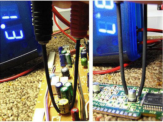 (Hi-fi audio board out of a 20 year old JVC HR-S5800.) Last edited by Ed in Tx; 06-20-2010 at 07:30 PM.
|
|
#45
06-27-2010, 10:19 AM
|
|||
|
|||
|
Hi Ed,
An ESR meter is one of very pew pieces of gear I haven't acquired yet, and thanks for the tip. I'll try to get one as soon as budget permits. Looking at the service manual for my BR-S822U, there are 4 SMD electrolytics (.47 uF) that appear to deal with the headswitching on the flying PRE/REC board. I'm tempted to temporarily swap standard electros (all I have in stock) just to see what happens. These 4 electros appear to be in identical circuits, looks like they all supply DC control voltages to op amps inside the UPC2320GS chip on the flying board - but this is strictly a half-educated guess. There's also a control signal that comes from the slip ring, but I admit that I've traditionally been a "belt and tire" guy and haven't studied the deeper areas of VCR electronics to know what this control signal should be or where it comes from. I should have all the equipment I need to troubleshoot - just need a bit more knowledge which I will study as time permits. But since the 4 electros in question are in identical circuits, maybe I can do a quick-and-dirty comparison of capacitance before pulling anything up. Here's a schematic of the flying preamp board: www.barrys8trackrepair.com/PreBoard.html Sorry it's not the clearest. Have a great Sunday!
|
| Audiokarma |
 |
| Thread Tools | |
| Display Modes | |
|
|






 Linear Mode

