
|
|
|
|
|
#1
 05-11-2011, 04:53 PM
|
||||
|
||||
|
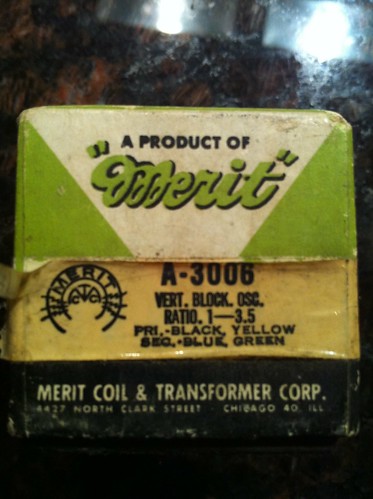
I cut through the transformer in haste and cut too deep totally screwing up the winding so I don't know if it was the leads or not. I did pick up a new vertical block oscillating transformer to replace it though. The impedance on the primary and secondary are lower than the original but I put it in and I'm going to hope it'll oscillate. I may have to tweak the circuit with resistors inline with the new transformer to make it linear but I'm crossing my fingers it'll be ok as is.
 Again I don't have a variac at home so I'll have to wait until tomorrow to fire it up and see what how I did. 
|
|
#2
05-11-2011, 06:26 PM
|
||||
|
||||
|
Sadly, if it doesn't work, adding resistors won't help- the transformer's magic comes from the # of turns of wire inside, not from the resistance of the coil; less resistance probably means fewer turns, unless the wire gauge is thicker than the original. (if you add a resistor, you make an RL circuit which behaves very differently from a coil by itself)
Also, if you can get replacement "magnet" wire [copper wire coated in enamel] of the same thickness as that of the original transformer (a yoke from a crap modern tube TV is a great place to get some), you could always give re-winding it a shot. It requires some patience and finesse, but it couldn't hurt to try if you can't get a good replacement for a reasonable price (i.e. reasonable hourly pay for how long you spend to wind your own), or are up for a challenge. It seems daunting, but it's not excessively difficult to try. To do that, the two magic numbers you need are a) the # of coil turns, and b) the total length of wire. Both of these can be obtained while you unwind the original. As pointed out before, you also need to pay attention to the polarity (winding direction) of the original. If you can match the winding pattern of the original, even better! Note that if A number of turns does not use near B amount of wire then something's wrong and you need to try again, unless it's because you use a different winding pattern. [I managed it with just matching the length of wire and winding pattern in an oscillator coil for my Fleetwood console (wire was ripped beyond repair, so I couldn't count turns and had to lay the pieces end to end to get length), and it worked... but I don't doubt a TV circuit is much more finicky, so YMMV]. I'd be happy to offer more details if you have questions... but no guarantees since I've only re-wound one coil myself, and that may just have been dumb luck! Last edited by VintagePC; 05-11-2011 at 06:32 PM.
|
|
#3
05-11-2011, 06:59 PM
|
||||
|
||||
|
I looked in my Merit catalog and they do list a replacement. It's an A-3003.
The A-3003 has a turn ratio of 1:4.2, the A-3006 that you have is 1:3.5. www.oldradioparts.com has the A-3003 for $7.00. They have a $25 minimum order. John Quote:
Last edited by jeyurkon; 05-11-2011 at 06:59 PM. Reason: spelling
|
|
#5
05-14-2011, 08:29 AM
|
||||
|
||||
|
Tried the transformer and got deflection!
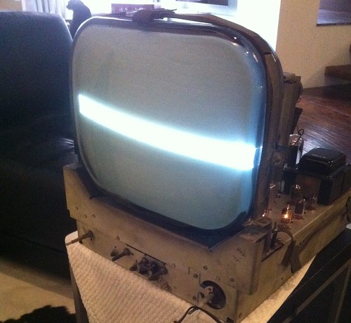 I'm emailing oldradioparts now to enquire about the correct transformer. Does any one else need any parts and want to go in with me to meet the $20 minimum order? I suppose I could always just give them $20 for the transformer instead of $7.
|
| Audiokarma |
|
#6
05-14-2011, 04:51 PM
|
||||
|
||||
|
Quote:
|
|
#7
05-14-2011, 04:52 PM
|
||||
|
||||
|
It might be a while until I get my hands on the correct transformer so I was thinking about working on another problem I have with the set. The picture above was taken from a side angle so it's not as obvious as when you look straight on at it, but the picture is skewed to the right and not level. Can any one point me in the right direction towards a fix for that? Is that something that I can work on now, or should I wait until I have the transformer and a full height picture?
I found another Majestic on Craigslist in my area with the same deflection problem...I wonder if that is a common thing with these sets. http://pittsburgh.craigslist.org/atq/2380646109.html Last edited by vts1134; 05-14-2011 at 05:03 PM.
|
|
#8
05-14-2011, 06:09 PM
|
||||
|
||||
|
I'd hold off until you have a new transformer. I've seen a few other threads here where people had no vertical, and the line often looked a bit skewed.
Once you have an actual picture, you can then display a test pattern/grid to aid in adjustments, and do all of the convergence/purity stuff in one swoop. If memory serves, you can "rotate" the picture by rotating the entire convergence assembly , as that will adjust the directions that the magnetic field deflects the beams. There are usually a set of rubber wedges under the yoke to keep it from moving. You should mark their positions before you remove them, otherwise your centering will be off when you reassemble. Here's an interesting read while you wait. This discusses purity adjustments on newer colour CRTs, but the principles behind it still hold. http://personalpages.tds.net/~rcarlsen/cbm/converge.txt
|
 |
| Thread Tools | |
| Display Modes | |
|
|





 Hybrid Mode
