
|
|
|
#61
 05-18-2011, 07:38 PM
|
||||
|
||||
|
Quote:
Also, on top of the one-hand-in-the pocket rule: if you have electrically insulating rubber gloves, put on one (or both, if you can work with them) just in case you forget and do take that hand out of your pocket. Safety first - Voltage hurts, current kills... and your body's resistance is futile. (Sorry for the pun... I'm terrible with them  ) )

|
|
#62
05-19-2011, 12:26 PM
|
|||
|
|||
|
To the OP:
At this point, and if you still have access to the variac, you might consider trying this: Disconnect both primary leads of the vert.out transformer and drive it directly with the variac. Granted it's a sine wave instead of sawtooth, but will tell you a lot. You should get very robust deflection, probably at around half to full line voltage. This will tell you the tranny and yoke coils are good, thereby proving the fault lies somewhere "upstream" of the tranny. If the problem remains, it's gotta be either in the tranny or the yoke (like a shorted turn that won't show up on a resistance check). Now disconnect the yoke winding and drive it directly with the variac (starting from a low setting). If deflection comes up, the yoke is good and by process of elimination, the fault would be in the tranny. Of course if the fault is "upstream" all bets are off. The first place i would look is the plate load resistor of the vert.oscillator, if you haven't already checked it. I can't see it since i don't have the schematic of your set, so this may not be applicable. But in many sets that resistor is a very common failure and worth bookmarking*. Its value goes 'waaay high due to being hammered by a high level pulse. Bill(oc) *Germaine to all makes and ages of '50s-'60s tube sets. Last edited by old_coot88; 06-09-2011 at 11:36 AM.
|
|
#63
05-19-2011, 01:48 PM
|
||||
|
||||
|
Quote:
BTW- What is The OP? Last edited by vts1134; 05-19-2011 at 04:22 PM.
|
|
#64
05-21-2011, 12:42 PM
|
||||
|
||||
|
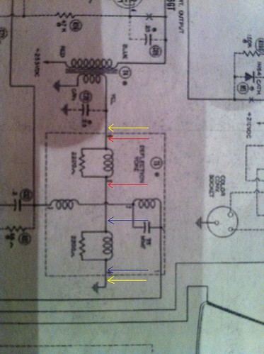
I think I need to back up and run a test that I don't think I did right before. I want to test the deflection coils to see if my problem is there. In the picture of the schematic below I tested continuity across the yellow wires. I'm not sure if that was right. I think I need to test across the red, and across the blue to test each coil. Can any one confirm that? If that is indeed what I need to do then my next problem is that I don't know how to test the two coils independently of each other. I apologize for leaning so hard on all of you to help me get this sucker up and running, but we all have to start learning some where I guess.
|
|
#65
05-21-2011, 03:01 PM
|
||||
|
||||
|
Looking at your picture, what you'd want to do is as follows. This will ensure you've tested the coils:
1. Disconnect/desolder the ground connection at the lower yellow arrow. (this ensures you test the coils themselves and not an alternate current path - note the other yellow arrow traces through the transformer and also to ground, resulting in two possible paths for the current to flow when you measure any two points in that line.) 2. Measure across the blue arrows. 3. Measure across the red arrows. 4. Reconnect the ground connection from step 1. It looks like you have resistors in parallel with your coils in the schematic. If that's the case, the resistance you measure should be 1/measurement = 1/(coil resistance)+1/(resistor resistance). Keep in mind the coil will have a fairly low resistance, so the reading is probably only a handful of ohms. With both resistor values the same, the red and blue measurements should be identical. If you measure anything different than expected, you'd need to disconnect one lead of the resistor to determine the culprit (coil or resistor) Last edited by VintagePC; 05-21-2011 at 03:04 PM.
|
| Audiokarma |
|
#66
05-21-2011, 03:32 PM
|
||||
|
||||
|
Quote:
|
|
#67
05-21-2011, 03:45 PM
|
||||
|
||||
|
Hmm... it might well be an inaccessible direct connection between the coils in the yoke itself. If that's the case, the best you can do for steps 2/3 is test across the yellow arrows. the result can indicate if coils are open. It won't indicate shorts because of the parallel nature of the circuit.
The AC/variac drive test mentioned above will give better information as to the state of the coils, since you get a visible result... If it does indicate a problem in the coils, the test I described would help narrow it down.
|
|
#68
05-21-2011, 05:17 PM
|
|||
|
|||
|
Quote:
Quote:
To the OP (original poster): is the capacitor across that winding (shown with dotted lines) actually in the set? If so, have you replaced it and/or verified that it's not shorted? oc
|
|
#69
05-22-2011, 04:09 PM
|
||||
|
||||
|
Quote:
The secondary of the transformer is good. The third question about the capacitor across the winding in the schematics I cannot answer. I didn't see that before you mentioned it. It says that it's 75mmf, but it's not listed in the part list. Could that also be located inside the yoke housing?
|
|
#70
05-22-2011, 05:57 PM
|
||||
|
||||
|
Quote:
The only time you'd read ~4400 ohms is if both coils are open. If you read ~2200, one coil is open. If you read something closer to zero, then the coils are probably OK (but you can't infer anything about the state of those resistors - see my parallel resistance calculation in the previous post). BTW, if you can see those two resistors sticking out of the yoke or anywhere on the chassis, it gives you some test points for your red/blue arrows. Quote:
Then, see if some AC appears on the chassis ground. If so, that capacitor is hiding somewhere and passing AC (or it might be shorted). If not, it's probably not there. Also, look at the connections running in to the yoke - there should be 4, two for vertical, and two for horizontal. (You may see only 3 if the lower ground is directly accessible from the yoke. If you see more/fewer, it may indicate additional components have been hidden... try to trace them on the schematic to find out what those wires do.
|
| Audiokarma |
|
#72
05-23-2011, 03:06 PM
|
||||
|
||||
|
Quote:

|
|
#73
05-23-2011, 05:42 PM
|
||||
|
||||
|
Old Coot- Are you referring to the capacitor just above the dotted lines indicating the yoke in my picture? The schematics say that it's C70 and rate it at .25mmf at 200v. The thing is I can't find it on the schematic pictures of the top and bottom of the set that indicate where everything is. Jeyurkon maybe you can confirm that?
The schematics make me think that the capacitor would live at the end of the right hand yellow arrow in the picture below.  As you can see there is nothing there but a termination point for the wire coming from the secondary of T4 and from the vertical coils. I had mentioned this in an earlier post and postulated that maybe it was just there just to make my job easier. Is it possible that it is just missing from the set? That seems improbable to me.
|
|
#74
05-23-2011, 06:24 PM
|
||||
|
||||
|
To what are those two little "domino" looking things connected? (hiding behind the big resistor that's dead center.). Those are mica capacitors, and it looks like they have one lead on the left-hand connector to which an arrow points.
Also, if that orange-brown square with three leads coming out of it is connected to anything relevant, beware that those are usually a package containing a resistor and capacitor network. It doesn't look like it's attached, but just something to keep in mind. Some schematics show the separate components, some show a "magic box", and others will show the internal components outlined with a dashed-line box. It's also possible that that capacitor is hiding somewhere in the yoke, especially if there's a nearby accessible ground point to which they could run it... It could well be bridging BOTH deflection coils to the ground connection on their other side. Since most capacitors short on failure (unless they're special line safety caps), the AC test I mentioned will show if it's present regardless of condition... and at least knowing that eliminates some of the guesswork.
|
|
#75
05-23-2011, 06:49 PM
|
||||
|
||||
|
The parts list has an asterix next to C70. "Not used in all models." Also a note symbol and dotted line in the schematic.
Phil Nelson
|
| Audiokarma |
 |
| Thread Tools | |
| Display Modes | |
|
|





 Linear Mode

