
|
|
|
#1
 08-19-2011, 12:52 AM
|
||||
|
||||
|
"Li'l 7" AM Transmitter
A few weeks ago I completed a "Li'l 7" transmitter from the schematic and instructions on Phil's Old Radios, http://antiqueradio.org/transmitter.htm
 I designed my variant of the Li'l 7 so that the whole chassis lifts from the enclosure without even removing any knobs.  It looks great...but it doesn't work! I've gone over every connection and every wire three times, tested continuity wherever I could, tracked the input from my CD player to the tube, and tried multiple frequencies on two different radios. I also learned that it's not a good idea to discharge a capacitor into your headphones. The only variation from the original design is that I used two 68 mfd caps in place of the specified 22 mfd caps, but I don't think that should make much difference. I'm hoping there's something obvious that I've overlooked. The link above to Phil's website shows the schematic and description. I don't know what to do next. Any suggestions? - Winky 
|
|
#3
08-19-2011, 09:13 AM
|
||||
|
||||
|
The most likely problem may be that you have to swap the connections on L1, but only the primary OR the secondary. Get it wrong and the oscillation won't happen.
From Phil's website: 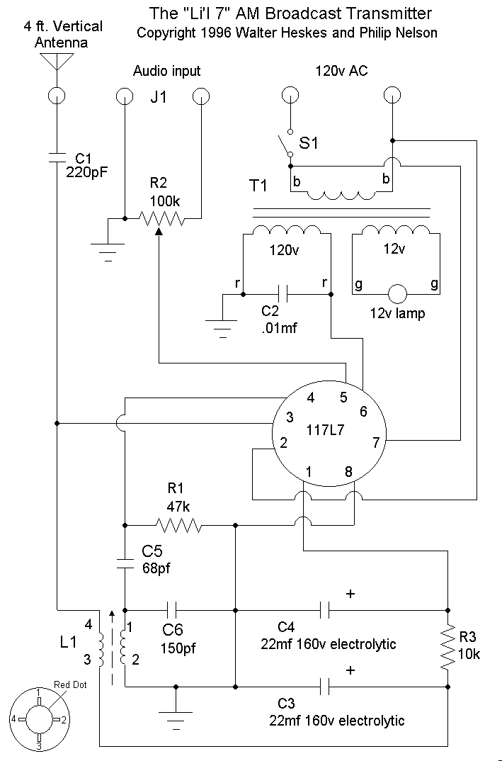 Check that you wired to the correct tube socket pins. You might have shifted by one by mistake. And I'm sure you know this, but tube pinout diagrams are viewed from the bottom of the socket, where you'd be looking when wiring the socket below the chassis, unlike IC pinout diagrams.
__________________

|
|
#4
08-19-2011, 09:50 AM
|
||||
|
||||
|
I am getting proper voltages as far as I can determine, I have rechecked the L1 contacts and the 117L7 pins numerous times. In fact, I let it sit two weeks and then rechecked everything again before I decided to post this question. This weekend I'll do it again and chart voltage readings. I'll probably record a lot of worthless values, but maybe I'll hit on something significant.
Thanks. - Winky.
|
|
#5
08-19-2011, 02:52 PM
|
||||
|
||||
|
Quote:
Nice job of construction, by the way. Once you get your transmitter working, send me a PM if you would like me to include a photo or two at the end of that article. Phil Nelson http://antiqueradio.org/index.html P.S. As a last resort when debugging a project, I put away the original schematic and draw a new one by hand, looking only at what I have built. This forces you to look at things with fresh eyes. It's still maddeningly easy (for me, at least) to overlook a small mistake. Last edited by Phil Nelson; 08-19-2011 at 02:58 PM.
|
| Audiokarma |
|
#6
08-20-2011, 01:22 AM
|
||||
|
||||
|
Freshly Drawn Schematic
Rechecked every connection against Phil's schematic with special attention to the tube and the RF coil. The coil is exactly as originally described by Phil, and it included a diagram showing the red spot and the terminal numbering. Recorded voltages at pins 1-8 and rechecked the continuity across every accessible connection. Also verified that each component is the correct value. Then I followed Phil's suggestion--made my own schematic directly from my own appliance. This is what I came up with:
 Variations from original schematic are (1) C3 and C4 68mfd, (2) fuse, and (3) rotary switch for C6a/b/c. Any glaring errors? - Winky
|
|
#7
08-20-2011, 06:36 AM
|
||||
|
||||
|
I'd find it helpful to draw the internal parts of the tube on the diagram. It's easier to trace that way than to stop and think: hmm..pin 5 goes to ..what? Forgive me for this really obvious suggestion, but do both parts of the tube test good?
I know you've gone over the wiring time after time, but something I've found helpful is to trace each circuit and then mark them off one by one with a highlighter on a copy of the schematic. I have a 1920's TRF on the bench right now that somebody had got into and this is helping me get the wiring back to original.
__________________
Reece Perfection is hard to reach with a screwdriver. Last edited by Reece; 08-20-2011 at 06:47 AM.
|
|
#8
08-20-2011, 10:02 AM
|
|||
|
|||
|
Wink, as a helpful suggestion, a schematic should always show the internal elements of a tube (or other active device like a transistor as the case may be). A quick Google under 'Vacuum tube symbols' and 'Electronic symbols' would probably yield a lot of good info.
BTW, that's a gorgeous resto you did on the Stromberg Carlson radio.  If i may, being a cantankerous old fuddyduddy, i'd like to air a perennial gripe (again) about vacuum tube nomenclature. That's in the usage of the terms "filament" and "heater". Back in the day, for a techie to use those terms incorrectly earned a demerit and severe reprimand.   A tube with an indirectly heated cathode uses a heater, not a 'filament'. Whereas when the filament is the cathode and the direct emitter of electrons, is simply called the filament. Off soapbox now. 
Last edited by old_coot88; 08-20-2011 at 02:35 PM.
|
|
#9
08-20-2011, 10:37 AM
|
||||
|
||||
|
At the very least, L1 has to be drawn incorrectly in the above.. From the info provided, I'd suspect one winding goes from pin 1 to 2, the other 3 to 4. Not having the 117L7 diagram handy, I'm guessing on the interconnects. It looks (from the voltage readings) like it's not conducting.. (ref to the 8V "drop" across the 10K filter resistor.. (Less than 1mA) I'm also assuming that the heater is working? (Either visual inspection, or does the tube envelope heat up after a bit?) I also agree with the above suggestion, does the tube test good?
|
|
#10
08-20-2011, 01:07 PM
|
||||
|
||||
|
I'm working on it.
I apologize for my gaffe in failing the schematize the tube. I was going to do that, but that's where I would likely make an error in the schematic. I can figure out cathodes, heaters, plates, but I only have vague concepts of screens, grids, and bias. I give it a try, though. My hope was that we could assume that Phil's original diagram is accurate and see if my schematic matched his pin numbers.
For Reece, I like your method of tracing over the schematic. In fact, you can see below how I did that myself. If the adage is true, that "Great minds think alike," then you must have a truly staggering intellect.  The tube is new from AES, and I assume (I think I've made too many assumptions) it's OK. Unfortunately I misplaced my tube tester, but I might have just left it in my pants pocket, so I'll check through the laundry later. Sorry, I don't mean to be facetious. Earlier this week I visited my usual 1960s-era electronic supply with the tubes from the Atwater Kent 37 and neglected to bring the 117L. However, after testing the first five tubes "bad," Alan the proprietor said, "I think my tester's bad--not the tubes." I have one other place to try when it opens next week. I've been trying to cultivate a supportive network, but this isn't exactly like Chicago. I drove 40 miles just to have Alan tell me his tube tester was bad. I met a guy who could help me with this stuff, and I was looking forward to working with him, but he didn't answer my last email some months ago. There's a VK member in my area, and he hasn't answered my email either. Is it my breath? Well, I'm done venting. Thanks to everyone for the tolerant, patient assistance. I still have to digest teevee's comments, so I'll get to work sorting out the mysteries of the vacuum tube. - Winky
|
| Audiokarma |
|
#11
08-20-2011, 03:33 PM
|
||||
|
||||
|
Quote:
Looks like you are seeing rectifier tube action, so the tube is probably good. PHP Code:
__________________
Last edited by wa2ise; 08-20-2011 at 03:37 PM.
|
|
#12
08-20-2011, 04:53 PM
|
|||
|
|||
|
"Knock a buzzard off a sh**wagon." Gotta remember that gem.

|
|
#13
08-20-2011, 07:00 PM
|
||||
|
||||
|
Enhanced Schematic
I added the innards of the tube to the schematic. I do get 125V from pin 2 to pin 7, and the singed hair on my knuckles indicates that the heater is working. Sometimes I can learn something from tube data sheets, so I downloaded RCA and Tung-Sol sheets, but I've gained little from that. I keep jumping from one question to the next, and I thought it best to post the revised schematic now instead of waiting for a revelation.
 There seems to be a consensus developing that I've mixed up the coil terminals. It'll take me a while to follow up on the latest advice. Gotta cook dinner now. Thanks. - Winky.
|
|
#14
08-20-2011, 09:31 PM
|
|||
|
|||
|
Hmm. Assuming the circuit is wired as shown, the first thing that jumps out is that the B+ supply is shorted to ground through the primary of the coil (lugs 2 and 3). Assuming that that coil has continuity (not open), resistor R3 would be really smokin' (assuming it's 1/2 watt rating). What voltages do you have at the top of filter caps C3 and C4?
Last edited by old_coot88; 08-20-2011 at 09:35 PM.
|
|
#15
08-21-2011, 01:08 AM
|
||||
|
||||
|
Li'l 7 Schematic, Version 3.0
I corrected the schematic of the RF coil--I had placed the numbers arbitrarily. Now I think they'll make sense. Following is the P-C70-RF instruction sheet, the latest revision of my schematic, and a picture of the coil showing how the terminal numbers were determined.
   Voltage and resistance data for the coil: Terminal 1 to chassis ground: 0V Terminal 2 to chassis ground: 0V Terminal 3 to chassis ground: -156V Terminals 4 to chassis ground: -156V Resistance terminals 1-2: 10 ohms Resistance terminals 3-4: 78 ohms (Curiously, when I use the continuity tester between 3 and 4 I get an "open" reading or an occasional quick flash of "short.") Voltage at C3: -156V Voltage at C4: -165V I see how my error misled everyone. If I've made any other errors in the schematic, it's clearly the fault of the United States Congress and the previous Presidential administration. I considered trying the connection swapping, but I found it too confusing to follow the advice based on the erroneous schematic. With sincere appreciation, - Winky
|
| Audiokarma |
 |
| Thread Tools | |
| Display Modes | |
|
|


 Linear Mode

