Videokarma.org

Go Back   Videokarma.org TV - Video - Vintage Television & Radio Forums > Early B&W and Projection TV

Notices

We appreciate your help

in keeping this site going.
Reply
 
Thread Tools Display Modes
  #1  
Old 04-20-2012, 11:41 AM
cdmarion's Avatar
cdmarion cdmarion is offline
VideoKarma Member
 
Join Date: Jul 2007
Posts: 150
Admiral Triple Thrill help needed.

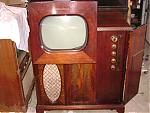
I've got a 1949 Admiral Triple Thrill tv chassis 3OA1-C, I've done a total re-cap but still have no picture, I haven't measured voltage at the picture tube anode but I have done the screw driver test and get a pretty good pop from the anode along with an arc about 1/2 inch long at the cap of the HV rectifier tube so I know HV is present. All tubes test good, I've measured a number of tube pins, all of the power chassis tubes are within spec, However V10 the 6K6 video output tube readings are off, P3 plate voltage is at 90vdc should be at 105vdc, P5 grid should be at -1.4vdc but it's at -6vdc, finally p8 cathode should be at 50vdc but it's at 6vdc. Any Ideas what could be causing this?

Also I've got two rather large resistors that are now shown in the schematic, can anyone give me an Idea what the values would be? I've attached pics.

The photofact # is Date 3/49-495-2 Set 57 No.2
Attached Images
File Type: jpg IMG_0703.jpg (121.5 KB, 31 views)
File Type: jpg IMG_0704.jpg (87.0 KB, 36 views)
Reply With Quote
  #2  
Old 04-20-2012, 11:42 AM
cdmarion's Avatar
cdmarion cdmarion is offline
VideoKarma Member
 
Join Date: Jul 2007
Posts: 150
I should clarify, no raster, screen is completely dark.
Reply With Quote
  #3  
Old 04-20-2012, 12:15 PM
Electronic M's Avatar
Electronic M Electronic M is offline
M is for Memory
 
Join Date: Jan 2011
Location: Pewaukee/Delafield Wi
Posts: 15,446
I'd check the voltages at the CRT socket. If any are over 20% off of proper value, and tweaking the brightness and contrast controls does not bring it into line then check every part connected to that CRT lead.

Another possibility is that the CRT has 0 emissions and will need to be replaced. It could save you some head scratching if you test the CRT on a proper tester before diving into circuit trouble shooting.
__________________
Tom C.

Zenith: The quality stays in EVEN after the name falls off!
What I want. --> http://www.videokarma.org/showpost.p...62&postcount=4
Reply With Quote
  #4  
Old 04-20-2012, 12:36 PM
cdmarion's Avatar
cdmarion cdmarion is offline
VideoKarma Member
 
Join Date: Jul 2007
Posts: 150
Quote:
Originally Posted by Electronic M View Post
I'd check the voltages at the CRT socket. If any are over 20% off of proper value, and tweaking the brightness and contrast controls does not bring it into line then check every part connected to that CRT lead.

Another possibility is that the CRT has 0 emissions and will need to be replaced. It could save you some head scratching if you test the CRT on a proper tester before diving into circuit trouble shooting.

I've tested the CRT and it test's fine, emissions are great. What I get at the CRT socket is as follows;

Published Measured
P1= 0V OV
P2=.5VDC 1.9VDC
P10=290VDC 316VDC
P11=20VDC 20VDC
P12=6.3VAC 6.4VAC
Reply With Quote
  #5  
Old 04-20-2012, 12:48 PM
Eric H's Avatar
Eric H Eric H is offline
Administrator
 
Join Date: Jun 2002
Location: So. Calif
Posts: 11,565
Is the Ion trap on the tube?
Reply With Quote
Audiokarma
  #6  
Old 04-20-2012, 12:57 PM
mstaton's Avatar
mstaton mstaton is offline
"Book em Dano!"
 
Join Date: May 2011
Location: Caldwell, Id
Posts: 1,609
You should replace that sand resistor and that bumblebee cap that's hiding under it.
__________________
"It's a mad mad mad mad world" !!
http://www.youtube.com/user/mwstaton64?feature=mhee
Reply With Quote
  #7  
Old 04-20-2012, 01:48 PM
cdmarion's Avatar
cdmarion cdmarion is offline
VideoKarma Member
 
Join Date: Jul 2007
Posts: 150
Quote:
Originally Posted by Eric H View Post
Is the Ion trap on the tube?
The ion trap is on the tube, it has a blue and a black strap, does it matter which end is closest to the socket?
Reply With Quote
  #8  
Old 04-20-2012, 01:49 PM
cdmarion's Avatar
cdmarion cdmarion is offline
VideoKarma Member
 
Join Date: Jul 2007
Posts: 150
Quote:
Originally Posted by mstaton View Post
You should replace that sand resistor and that bumblebee cap that's hiding under it.
Thats one of my issues, I cant find the sand resistor on the schematic, I'm not sure of the value of this resistor, not sure what to replace it with.
Reply With Quote
  #9  
Old 04-20-2012, 02:00 PM
cdmarion's Avatar
cdmarion cdmarion is offline
VideoKarma Member
 
Join Date: Jul 2007
Posts: 150
Here's some pic's of the sand resistor. It looks like 6 W10, any thoughts? I measures 3.27K but i'm assuming its bad anyway. Just dont know what to replace it with.
Attached Images
File Type: jpg IMG_0705.jpg (38.8 KB, 13 views)
File Type: jpg IMG_0706.jpg (63.5 KB, 13 views)
Reply With Quote
  #10  
Old 04-20-2012, 02:07 PM
bandersen's Avatar
bandersen bandersen is offline
RCA 741PCS
 
Join Date: Mar 2009
Location: Chicago, IL
Posts: 8,817
Quote:
Originally Posted by cdmarion View Post
The ion trap is on the tube, it has a blue and a black strap, does it matter which end is closest to the socket?
Yes, black closest to socket.
__________________
Here are my Vintage Radio & TV YouTube Channel and Photo Gallery

Last edited by bandersen; 04-20-2012 at 02:23 PM.
Reply With Quote
Audiokarma
  #11  
Old 04-20-2012, 02:12 PM
cdmarion's Avatar
cdmarion cdmarion is offline
VideoKarma Member
 
Join Date: Jul 2007
Posts: 150
Quote:
Originally Posted by bandersen View Post
Yes, black closest to socket.
Thats how I've got it installed
Reply With Quote
  #12  
Old 04-20-2012, 02:23 PM
bandersen's Avatar
bandersen bandersen is offline
RCA 741PCS
 
Join Date: Mar 2009
Location: Chicago, IL
Posts: 8,817
I have four unrestored 30A1 chassis and just can't find those two resistors. The one you show in the horizontal circuitry in the second photo near a 33K resistor seems especially out of place.
There's nothing there in my chassis I suspect those are old repair attempts.

This chassis came out of a Triple Thrill set. You can click on the photo to get a larger version.
__________________
Here are my Vintage Radio & TV YouTube Channel and Photo Gallery

Last edited by bandersen; 04-20-2012 at 02:28 PM.
Reply With Quote
  #13  
Old 04-20-2012, 02:51 PM
cdmarion's Avatar
cdmarion cdmarion is offline
VideoKarma Member
 
Join Date: Jul 2007
Posts: 150
Quote:
Originally Posted by bandersen View Post
I have four unrestored 30A1 chassis and just can't find those two resistors. The one you show in the horizontal circuitry in the second photo near a 33K resistor seems especially out of place.
There's nothing there in my chassis I suspect those are old repair attempts.

This chassis came out of a Triple Thrill set. You can click on the photo to get a larger version.
I agree with the old repair attempts theory. I'm going to cut these out and give her a whirl. Lets see what happens. Thanks for the pic.
Reply With Quote
  #14  
Old 04-20-2012, 03:38 PM
cdmarion's Avatar
cdmarion cdmarion is offline
VideoKarma Member
 
Join Date: Jul 2007
Posts: 150
My schematic refers to the two resistors mounted on the lower side of the chassis, looking at the pic's above. My receiver has neither mounted there, there is R88 a 5000ohm 5W and R37 a 3000ohm 15W. I'm sure these are the ones in my set just don't know why they're mounted where they are.
Reply With Quote
  #15  
Old 04-20-2012, 04:06 PM
bandersen's Avatar
bandersen bandersen is offline
RCA 741PCS
 
Join Date: Mar 2009
Location: Chicago, IL
Posts: 8,817
Yeah, you definitely need them. I believe one was originally a candohm riveted to the chassis. Those have a tendency to go bad. It's been replaced in all four of my sets. Here's another one for comparison.

__________________
Here are my Vintage Radio & TV YouTube Channel and Photo Gallery
Reply With Quote
Audiokarma
Reply


Thread Tools
Display Modes

Posting Rules
You may not post new threads
You may not post replies
You may not post attachments
You may not edit your posts

BB code is On
Smilies are On
[IMG] code is On
HTML code is Off

Forum Jump


All times are GMT -5. The time now is 10:41 AM.


Powered by vBulletin® Version 3.8.4
Copyright ©2000 - 2026, Jelsoft Enterprises Ltd.
©Copyright 2012 VideoKarma.org, All rights reserved.