
|
|
|
#31
 05-15-2012, 01:48 PM
|
|||
|
|||
|
yep that would get messy oh well maybe someday somebody will find a micro connector that is no larger than the wire itself. Too bad, it would be nice to be able to easily separate the pcb for easy access.

|
|
#32
05-15-2012, 07:27 PM
|
||||
|
||||
|
Well, the Molex female terminals are about as small as anything can get and still allow you to solder onto it. A few of the board's WW pins would be easy, since the old leads have enough slack to simply attach a Molex terminal on the end. A number of leads are tight and would need lengthening. There are at least three WW pins with two wires attached.
Meanwhile, the new K7 couplate works fine, but the height is still deficient.  The 400V boost voltage measures 400V on the money. On the 6DR7 vertical tube, the voltage at the oscillator grid is low (-.03V rather than -3.5V) and the plate is somewhat high (155V rather than 115V). As with the horizontal section, caps & resistors around that tube have already been replaced, which leaves couplates K4 and K5, I guess. Phil Nelson
|
|
#33
05-22-2012, 01:27 PM
|
||||
|
||||
|
I've been puttering around with the height problem, still seeking a solution. Height is 1/3 of the screen at most, and linearity is poor.
I wonder if the vertical output transformer could be funky? I have subbed known-good 6DR7 vertical tubes, replaced the K4 and K5 vertical couplates, checked or replaced Rs and Cs around that tube. The pots for hold, height, and linearity are working and have the right resistance. The 400V boost voltage is normal. Here's a piece of the Sams schematic:  Voltages are close except that pin 7 (grid) is only -0.5 volts rather than -3.5. Resistance of the vertical windings on the yoke looks normal. On the vertical output transformer, the secondary measures 2.6 ohms (expected 2.5) but the primary measures 410 ohms where it should be 425 (or 430 in the Philco schematic). Could a few shorted turns in the output transformer account for the lack of height? I feel like I've eliminated just about everything else. This problem existed before I did any restoration. Phil Nelson Phil's Old Radios http://antiqueradio.org/index.html
|
|
#34
05-22-2012, 06:01 PM
|
|||
|
|||
|
Some things to try:
Bridge the 100 mfd cathode bypass. Rotate v lin while measuring cathode, pin 9. It should go to 0 at extreme end Bridge electrolytic on the 275 volt source Recheck cap values that were replaced. C 40 will have most effect on height. Height and lin pots and the .0015 (C43) were common failure points. The small pix accounts for the low neg voltage on pin 7 since the source is the output plate. Make sure pin 7 measures 68 k to ground.
|
|
#35
05-22-2012, 11:14 PM
|
|||||
|
|||||
|
Thanks for the ideas. Here's what I found.
Quote:
Quote:
Quote:
Quote:
I noticed one difference: R55 (between pin 8 and vert hold pot) should be 33K and I installed 39K for some reason. (Perhaps 39K is what I found there.) Not sure how important that is. I measure 8.6V on that pin; Sams calls for 7.5V and the Philco manual calls for 10V. Quote:
Regards, Phil Nelson Last edited by Phil Nelson; 05-22-2012 at 11:26 PM.
|
| Audiokarma |
|
#36
05-22-2012, 11:39 PM
|
|||
|
|||
|
Phil:
Agree that nothing seems out of range. 33K vs 39K will only affect vert hold range. It locks OK. The vertical output transformer could have some shorted primary. Check resistance with a DC meter, not a digital one. Some digital meters are fooled by high inductances because they use an AC voltage for resistance. Make sure the 100K 1W is not burned. It may be necessary to sub a VOT for test. You can try driving the output stage with about 20 VAC, 60Hz to see if it will sweep at all. It will be distorted, but it will give an indication.
|
|
#37
05-23-2012, 12:52 AM
|
||||
|
||||
|
I hauled out my trusty old analog Triplett meter. The primary measures lower, if anything -- 400 ohms, give or take a couple. This is measuring from pin 1 of the VOT to test point 33 (275V source) in Sams.
The 100K/1W resistor (R60) is new and it measures 100K. I just remembered that my BK 1077B Analyst can provide a vertical plate drive signal. (I need to use that thing more often!) Tomorrow, I'll pull the VOT and see what happens with that signal. Regards, Phil Nelson
|
|
#38
05-23-2012, 11:01 AM
|
|||
|
|||
|
Quote:
 I was fixing to suggest what Don L just suggested.. drive the output stage with AC. I was fixing to suggest what Don L just suggested.. drive the output stage with AC.
|
|
#39
05-23-2012, 11:54 AM
|
||||
|
||||
|
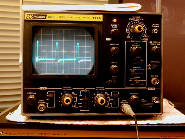
OK, the vertical plate drive signal from the 1077B looks like this:
 I removed the 6DR7 vertical output tube and injected the Analyst's vertical plate drive signal on pin 1. Here, the 1077B's Amplitude control is set about midway: 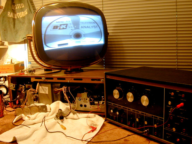 The height's about the same as before, with linearity very compressed toward the bottom. Cranking up the Amplitude control nearly fills the screen: 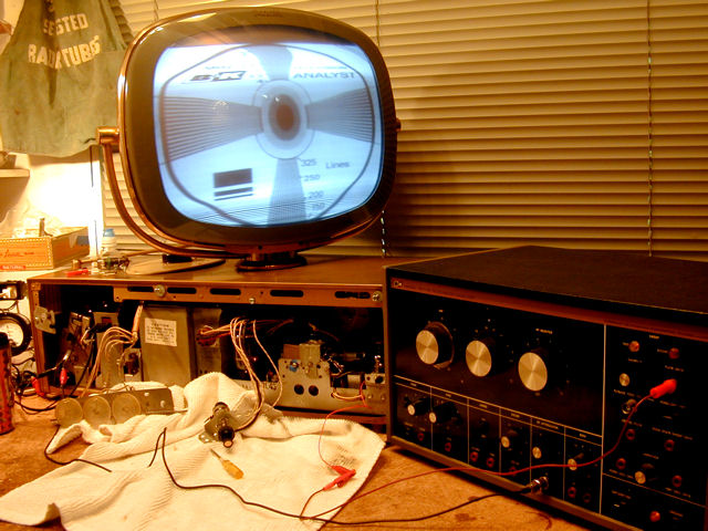 Phil Nelson
|
|
#40
05-23-2012, 02:21 PM
|
||||
|
||||
|
Phil, can your Analyst generate a signal to inject on the grid of the vertical output tube? Reason I ask, is that you still could have shorted turns on the vertical output transformer, and turing up the Analyst output would cover it up, sort of speak. The sam's says "do not Measure" so you don't know what the amplitude of the plate waveform should be. But the grid drive is shown. But it's inverted compared to the plate's, as you'd expect. If your analyist can make a grid waveform, dial in the amplitude, and disconnect the coupling cap C42 from the vert osc circuit and inject it via that cap to the output triode grid there. And see if the height is good.
__________________

|
| Audiokarma |
|
#44
05-23-2012, 03:24 PM
|
|||
|
|||
|
It also looks like it is borrowing some neg bias from the horz out grid circuit. I would check R58 and R59 which makes up a voltage divider for the bias and also scope the grid of the 6DR7 pin 2-3. sometimes the neg voltages at the pins can be misleading esp if that bias supply is goofed up due to a faulty divider network (R58/R59). oh and check C50 the .22 cap that looks like it filters that bias supply.
|
|
#45
05-23-2012, 04:45 PM
|
|||
|
|||
|
Test the bias divider:
1. Turn down brightness 2. Remove 6DR7 3. Measure grid, pin 3 It should be roughly half of the 6DQ6 grid bias or about 22 volts. That saves unsoldering some parts.
|
| Audiokarma |
 |
| Thread Tools | |
| Display Modes | |
|
|


 Linear Mode

