
|
|
|
#61
 05-29-2012, 03:14 PM
|
||||
|
||||
|
According to my scope manual, that vertical setting is 5 volts per square, so 6 squares in the previous photo would equal 30 volts, but I don't use a scope to measure voltage, so don't count on me having it set up correctly for that.
I turned down the Height control to reduce the pin 3 grid voltage to around -20V as given in the manuals and connected my DMM as well as the scope. This photo shows the voltage reading and waveform at pin 3 (compare to waveform W8 in the Sams manual):  Without changing the Height control or scope settings, I switched the probes to the pin 6 plate (compare to waveform W7 in Sams):  Pin 3 voltage is about -21V (Sams says -20V) and Pin 6 voltage is about 131V (Sams says 115V). The Philco manual calls for 130V on pin 6, so the measured 131V is good enough for me. Executive summary: on that plate and grid, the waveforms match the models and the voltages look OK, but the height is still badly deficient -- about 2 inches high. Great picture, otherwise. Phil Nelson 
|
|
#63
05-29-2012, 03:37 PM
|
|||
|
|||
|
you should be able to calibrate the scope if it has a test point on the scope, generally a .5v square wave. then you adj the center of the voltage knob to make if fill one square when its set to 500mv. OR your can just use a 9v battery, set the scope to DC and see if you get apporx 2 squares of rise when set to 5v
|
|
#65
05-29-2012, 07:52 PM
|
||||
|
||||
|
Here are the 6DR7 resistance readings.
1: 406 ohms (measured from 275V B+ source) 2: 1.97 megohms 3: 1.97 megohms 4: .1 ohm 5: zero 6: 1.68 megohms (measured from 275V B+ source) 7: 67.3 K ohms 8: 51 K ohms 9: 217 ohms The resistance on 6, 8 and 9 varies with control settings. The R63 thermistor is behind the yoke. I shorted it out with a jumper and tried the set. No change in height. Phil Nelson 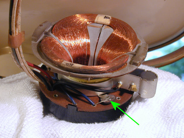 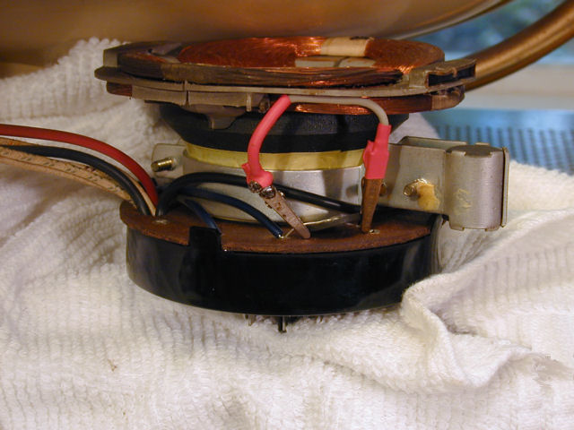
|
| Audiokarma |
|
#66
05-30-2012, 10:51 PM
|
||||
|
||||
|
I checked the scope's vertical calibration using its native signal (jack at upper right), a 0.5V square wave. With the Chan B vertical control set to 0.1V/cm, the trace is about 5 squares high, so 5 x 0.1V = 0.5V. Things add up.
 Then I changed the Chan B control to 5V/cm and checked pin 3 of the 6DR7 with a couple of meters (an old Voltohmyst VTVM and a new Fluke DMM). I left the photos full size so you can read the dials & meter settings. The meters show -20V to -21V, and the scope seems to agree (4 squares x 5V = 20V). Things still add up. http://antiqueradio.org/art/6DR7Pin3...ystVoltage.jpg http://antiqueradio.org/art/6DR7Pin3FlukeVoltage.jpg I left the vertical control unchanged -- still at 5V/cm -- and then checked pin 6. The meters agree, both showing around 130V. The waveform has the right shape, but if you count the squares, they don't add up to 130. http://antiqueradio.org/art/6DR7Pin6...ystVoltage.jpg http://antiqueradio.org/art/6DR7Pin6FlukeVoltage.jpg So, my VTVM gives the same readings as my DMM, for what that's worth. And my scope can give sensible voltage readings for some test points, but not pin 6 for some reason. I'm using a plain vanilla scope probe, 1x. Possibly I'm overlooking something obvious, or I don't have the right equipment to learn much more from measuring these points. Phil Nelson
|
|
#67
05-31-2012, 08:58 AM
|
|||
|
|||
|
Wunner if there could be a carbon track in the tube socket itself lugging down pin 6.

|
|
#70
05-31-2012, 11:06 AM
|
|||
|
|||
|
to further illustrate the point of scope reading for voltage compared to meters, read the test point with you meter, should be 2.5v not 5v PP as on the scope. the square wave duty cycle will avg out on the meter between 0 and 5v pp. since its duty cycle is the same on and off, the meter will just avg and give you 2.5. Sine waves are different scope PP will be 1.41 IIRC more than the meter. This is why you get 165 vdc out of a 120vac supply, the PP of the 120vac is actually higher, and when rectified and filtered it shows up.
when reading odd shape waves it gets really wacky. So sams gives both the meter voltage AND the PP to make it easy to see whats going on. I dont know the input impedence of modern DMMs prob as high as a VTVM, but I still prefer the VTVM again due to how odd shaped waved may effect the DMM. I do use the scope for reading DC voltages, like B+, you can use the DC setting to check voltage, and then look at the line for ripple. IF the DC is correct you can switch to AC and take a closer look at the ripple. Last edited by DaveWM; 05-31-2012 at 11:20 AM.
|
| Audiokarma |
|
#71
05-31-2012, 11:36 AM
|
||||
|
||||
|
If the meters are to be trusted on pins 3 and 6, then I'll quit fretting about them, since the meter readings match the specs and the waveforms are shaped correctly.
The final question concerns pin 7, the other grid, where the waveform looks correct (per Philco manual) but the voltage looks low, less than -1V where the manuals call for -3.2V to -3.5V. http://antiqueradio.org/art/6DR7Pin7...ystVoltage.jpg http://antiqueradio.org/art/6DR7Pin7FlukeVoltage.jpg As I understand it, the pin 7 grid returns feedback from the pin 1 plate. I have replaced the K5 couplate, which does the returning. I also replaced capacitor C43 (.0015/1KV) by wiring two .00033/630V caps in series to make one .00165/1260V. Since then, I got a ceramic .0015/1KV cap which I could substitute for C43 if the difference between .0015 and .00165 seems that critical. (Only a 10% difference, right?) On that part of the tube, the plate voltage on pin 6 is correct and the cathode voltage on pin 8 is in the ballpark (actual 6.5V; Sams 7.5V). Beyond that, I'm back my original question whether the output transformer is bad. I ordered a replacement from Moyer, so I'll soon be able to test that by substitution. Regards, Phil Nelson
|
|
#72
05-31-2012, 11:42 AM
|
|||
|
|||
|
I also replaced capacitor C43 (.0015/1KV) by wiring two .00033/630V caps in series to make one .00165/1260V. Since then, I got a ceramic .0015/1KV cap which I could substitute for C43 if the difference between .0015 and .00165 seems that critical. (Only a 10% difference, right?)
Phil Nelson[/QUOTE] 2 .00033 in series would be .000165 not .00165 off by a factor of 10x that would certainly cause problems. if that is the case it point to the reason why I alway check what comes out to what goes in on my old cap tester. even leaky caps will generally give a good enough value check to compare to new caps going in.
|
|
#73
05-31-2012, 11:48 AM
|
|||
|
|||
|
oh and would not trust the series 630's as a replacement for a 1000 anyway, that cap has a tough job dealing with all kinds of spikes etc... not sure if the voltage would evenly distribute across a series connection.
Last edited by DaveWM; 05-31-2012 at 11:54 AM.
|
|
#74
05-31-2012, 12:14 PM
|
||||
|
||||
|
Dang, I will go back and look at those caps to see if I really installed the wrong values or just mistyped the value now from bad memory.
Thanks, Phil "I was told there would be no math" Nelson
|
|
#75
05-31-2012, 12:16 PM
|
|||
|
|||
|
if you do need to replace it, I would pop for the film cap, the disc cap will prob be work fine, but may drift causing changes in vert height as it heats up (clearly if this is the problem).
|
| Audiokarma |
 |
| Thread Tools | |
| Display Modes | |
|
|


 Linear Mode

