
|
|
|
|
|
#1
 09-12-2014, 09:50 PM
|
||||
|
||||
|
All RCA TV's prior to 1952 used a split sound or non-intercarrier sound system. This means that the fine tuning is to be adjusted for best sound. Typically with these sets, the fine tuning is adjusted to the best sound much like any FM radio with a ratio detector or FM discriminator circuit. Typically as you adjust the fine tuning control from one end to the other, you will start with little or no sound, then weak sound through a null for best sound. As you continue turning the fine tuning knob, you will find a second null and then weak sound fading away as you reach the other end.
This means that the video and audio IF alignment can be a little tricky. The 721TS is a little simpler. But what you need to do is to adjust the local oscillator slug for best sound on the channel and then look at the picture. Proper alignment tools are better than using the VA62 for this, but it can be done with a VA62 with a little understanding and care. Just remember to optimize the sound first with the tuner local oscillator then address the video IF. I suggest it is best not to touch the sound IF and discriminator and see if you can tune to get good sound first then check the picture. I would like to add that RCA sets, especially the ones with four IF stages using the split sound design, although it is trickier to set up, will ultimately yield better pictures. This is because of the heavy sound attenuation at the at the video detector allowing wide bandwidth video with no sound patterning. Last edited by Penthode; 09-12-2014 at 09:56 PM. 
|
|
#2
09-14-2014, 03:04 PM
|
||||
|
||||
|
Had a chance to play around with the set a bit today. Decided to put the sound issue aside for now, and see what kind of picture I can get through a composite input. Following the RCA suggestion, I injected the video at the output of the video detector. I lifted the plate end of C103, and connected a 75 ohm terminating resistor from the free end to chassis ground. I injected a standard 1Vpp composite video signal across the added resistor. Picture looks acceptable, although the video level is just a touch too low. Cranking the signal up to ~1.5Vpp (or increasing the value of the 75 ohm terminator) gives full contrast range. Video frequency response is somewhat better without going through the IF strip, with details visible into the 4 MHz bar.
Also gave the original 10BP4 a try, to see what it looked like. Image was a bit on the dim side, but I guess that is to be expected with the fairly low accelerating voltage and non-aluminized tube. Certainly watchable in a darkened room. Sweep more than adequate to fill the 10" screen. Electromagnetic focusing coil and ion trap both working properly.  Have a total of 4 10BP4s here to choose from, so will go through them all with my CR31 and choose the best one for final assembly. Have a total of 4 10BP4s here to choose from, so will go through them all with my CR31 and choose the best one for final assembly.
Last edited by N2IXK; 09-14-2014 at 03:14 PM.
|
|
#3
09-19-2014, 03:48 PM
|
||||
|
||||
|
After testing the composite video and line audio input circuitry, I went ahead and did a permanent installation. I drilled 3 holes in the lower left area of the rear chassis skirt, to accommodate an RCA jack for audio input, a BNC jack for video input, and a small DPDT toggle switch to select between line input or off-air operation. The external audio gets injected right into the top end of the volume control., and the external video gets injected into the grid of the 1st video amp tube, via C103. Will label the added jacks and switch before final assembly.
I didn't see any need to have the input selector switch remove B+ from the IF stages in line input mode as the "Broadcast News" article shows. There doesn't seem to be any appreciable signal bleedthrough from a strong RF input signal when the line input is selected. This saves the need for a third pole on the switch, as well as the need to install a large wirewound resistor to replace the load normally drawn by the IF tubes and tuner. Next up will be to try tweaking the off-air audio in so it tracks better with the video. Got started on the cabinet work this week, as well. Cabinet was already stripped and veneer repaired/replaced, so the set essentially just needs a new finish put on, a missing safety glass replaced, and a few bits of metal trim polished up. Set is completely missing the "jewel" for the pilot light below the speaker. It wasn't in the box of knobs and loose parts that came with the set. Does anyone have a good picture of what it looks like, or, better yet, a spare unit they would part with? Looks to be about a 5/16" hole that it would mount in. Last edited by N2IXK; 09-19-2014 at 08:22 PM.
|
|
#4
09-26-2014, 12:24 PM
|
||||
|
||||
|
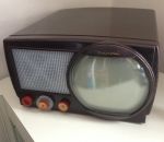
Finished up the cabinet work today. Disassembled the cabinet front completely, to repair a crack that split the grille into 2 separate pieces. Reglued a few areas of loose veneer and delaminating plywood, and gave everything a good sanding. Stained the cabinet sides, top, and front frame with Minwax dark walnut oil stain, with the speaker grille and CRT bezel in a lighter "gunstock" shade. The inner surface of the bezel and the mask behind the safety glass were done in a gold metallic paint, as per original. Stain covered with 5-6 coats of Minwax aerosol lacquer. I think it came out pretty well, considering my lack of experience doing this kind of work.
 Unfortunately, as it had already been stripped before I got it, the cabinet is missing the control label decals. I looked at the Radio Daze website, but couldn't find any suitable reproductions. Does anyone have a source for these? The missing "RCA Victor" decal under the screen was replaced with a brass logo plate of the same size which I salvaged from a 1948 model 8T241 which was too far gone to be anything but a parts source. Looks classier than a simple decal, IMO. The missing safety glass was replaced with a sheet of 1/4" polycarbonate plastic. All the cabinet needs to complete it is the jewel for the pilot lamp. Will leave the cabinet here in the shop for a while to allow the solvent smells to dissipate a bit before bringing it back home to reunite with the chassis and CRT. On the electronics front, I got on eBay and found a suitable vintage sweep generator so I can check and touch up the IF alignment as needed. Have never done an IF alignment before, but decided now would be a good time to learn.  Once the generator comes in, It will get its own cleaning and probable recapping, then hook it all up and see what gives with the sound issues. Chassis probably has 8-10 hours on it now playing through the added composite input, with no problems other than the failure of a 5U4G tube last night. Appears to be a bad solder joint on one of the filament pins. Have plenty of 5U4GBs to use, but the ST-bulbed "G" version just "looks right" in this set... Once the generator comes in, It will get its own cleaning and probable recapping, then hook it all up and see what gives with the sound issues. Chassis probably has 8-10 hours on it now playing through the added composite input, with no problems other than the failure of a 5U4G tube last night. Appears to be a bad solder joint on one of the filament pins. Have plenty of 5U4GBs to use, but the ST-bulbed "G" version just "looks right" in this set...
Last edited by N2IXK; 09-29-2014 at 06:53 AM.
|
|
#6
09-28-2014, 12:21 AM
|
||||
|
||||
|
Quote:
Phil Nelson Phil's Old Radios http://antiqueradio.org/index.html
|
|
#8
10-12-2014, 09:58 AM
|
||||
|
||||
|
Well, this should be the final progress report on this set. Got the sweep generator in and went through a complete alignment. It was a learning experience and took a bit of head scratching to get through, but the sound now nicely tracks with the video on all channels.
Thanks to a photo that Phil sent, I found a suitable pilot light jewel in my junkbox (from a scrapped Eico oscilloscope!), and installed it. Brought the cabinet home and reinstalled the chassis, speaker, and CRT. After tweaking everything to work with a 10BP4 rather than the 5" test tube, the set is playing in my living room, fed from the composite output from my satellite receiver. Only thing left to do is find some suitable wood screws to reattach the back, and move it into the corner where it will live. Will place an order for the control decals at some point to put the finishing touch on the project. Thanks to everyone who offered help and tips during this project!
|
 |
| Thread Tools | |
| Display Modes | |
|
|







 Hybrid Mode
