
|
|
|
|
|
#1
 11-01-2014, 04:07 PM
|
||||
|
||||
|
Quote:
The 2nd picture also looks like the scope ground had gotten poor, letting ground loop hum get into the trace.
__________________


|
|
#2
11-01-2014, 08:24 PM
|
||||
|
||||
|
My probe ground has always been the TV's chassis which I've always been concerned about since it always has something like 60v running through it regardless of the set being on or off. I've tested everything on the primary side. Even disconnected everything form the terminals of the plug on the back. It's almost like the socket itself has a leak but if you check there's no resistance under 20 megaohms.
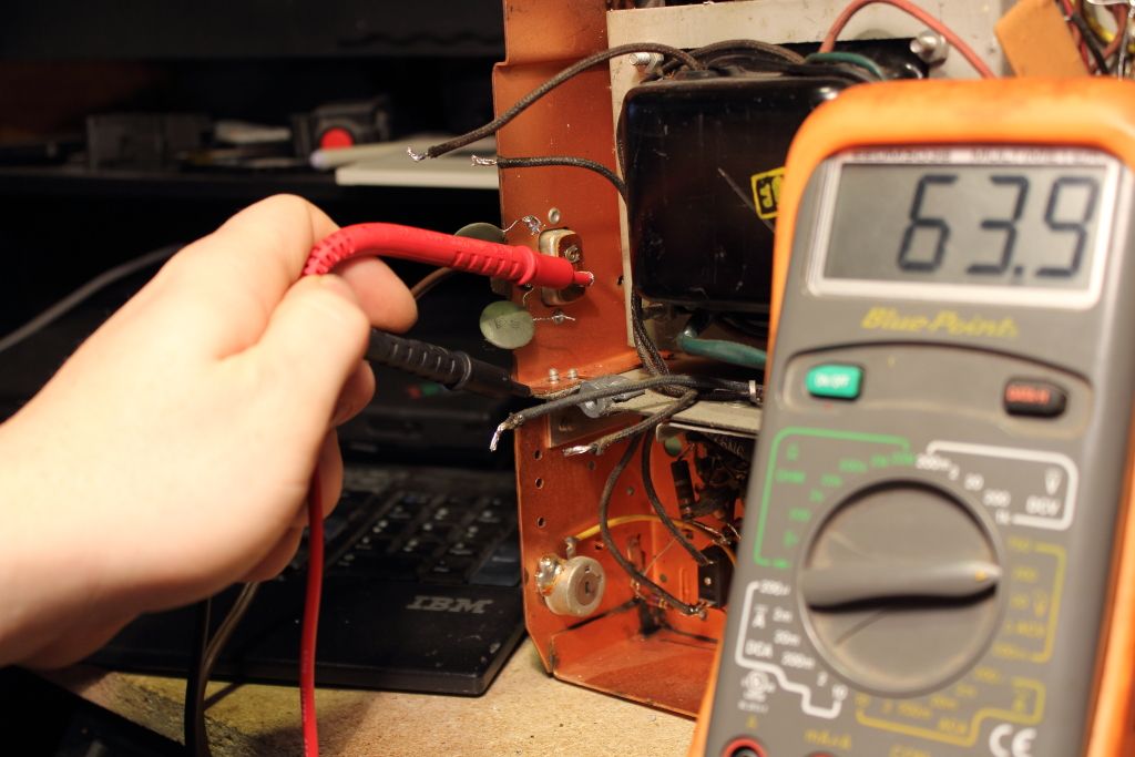 It's always entirely possible the bekelite insulator on the socket has broken down with time but god knows what adding 60v AC to the chassis has done. Last edited by MIPS; 11-01-2014 at 10:16 PM.
|
|
#3
11-02-2014, 07:42 AM
|
|||
|
|||
|
Hi Mips.
from what i gather without reading the schematic( gotta dig it out), most readings/waveforms use the chassis as ground for the test equipment with gear this vintage.check the footnotes on the schematic-it should say if the voltages/waveforms are taken with repect to chassis ground. from what i have seen from your pictures-the last problem is width...tv width looks acceptable-some of these vintage sets never had perfect width or control of width. i would try retaking those waveforms with the scope set in the "u" (horz)range? might see they match the expexcted waveform? iirc,1 horz scan line is aprox 63.5 us or microseconds or 1/15750 not sure at this point without looking at the schematic why you are getting 60 vac with respect to ground-i suspect you are using a isolation transformer while working on this set so should be safe but will get back to you once i dig schematic out. is picture good at this point other than width being a little wide? just some thoughts. RonL
|
|
#4
11-02-2014, 09:05 AM
|
||||
|
||||
|
The picture at this point is excellent aside from some ghosting (and that I can tell it is not from an excessively strong signal). The concern is that there is little to no width control and even on the pattern generator I can't make things fit so we're looking at an image that is around two inches too wide. I don't recall moving the yoke that far when I reinstalled the tube. Just a light adjustment to center the picture again.
I'm not running with an isolation transformer. With my knowledge of bakelite we should not be seeing a voltage being passed through the insulated socket at all (especially with these "low" voltages). If I knew where to source a replacement I'd try swapping it out. I've already zapped myself on this set several times because of it but nothing ever warned that this was a hot chassis. It raises a flag IMHO. I'm not hanging my scopes off this until we sort this voltage issue out. If you want to look at the schematics yourself I posted them back on the first or second page but here's a high-res version if you want to be able to read anything.
|
 |
| Thread Tools | |
| Display Modes | |
|
|


 Hybrid Mode
