
|
|
|
|
|
#1
 11-05-2014, 01:25 PM
|
||||
|
||||
|
Regarding issue #6, I had one CRT whose edges were noticeably brighter than the center area where scanning had occurred. In this photo I used tape to mark the boundaries.
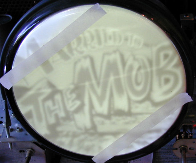 My solution was to rotate the CRT so that these areas were hidden by the mask (as they had been originally). I assumed that this was caused by long use. You can read more about this at http://antiqueradio.org/RCAT-100Television.htm . To test whether the phosphors in your CRT have faded, you can simply rotate your CRT a bit and see whether the shadow rotates, too. As you have figured out, it's normal with every round CRT for the extreme corners to be cut off. By definition, the TV image is a rectangle, not a circle. The mask on your TV also has rounded corners, so if you adjust height and width to just fit the mask, the extreme corners will still be hidden. That said, in your last photo the height and width seem excessive. I would normally expect to see all of that big circle. If you reduce the height and width -- as long as you don't create black bars around the edges -- you'll see more of the image. On some TVs, trying to achieve perfect geometry is a losing battle. I think some TVs were deliberately designed with a little overscan so that customers wouldn't constantly call the repairman when components aged and black bars appeared on the edges. And some sets give you more adjustment leeway than others. If you work with your adjustments long enough, you'll eventually find the best compromise for your particular TV. Then it is time to put away the test patterns and enjoy watching normal programs  Phil Nelson Phil's Old Radios http://antiqueradio.org/index.html Last edited by Phil Nelson; 11-05-2014 at 01:39 PM. 
|
|
#2
11-05-2014, 03:57 PM
|
||||
|
||||

Reminds me of the Cheech and Chong audio skit, where one of them pays a visit to see the other, the visitor asks what he's watching on TV. "It's a movie about Indians, but it's really boring". "That's not a movie, that's a test pattern".
 
__________________

|
|
#3
11-05-2014, 04:57 PM
|
||||
|
||||
|
Quote:
I agree that your set seems to overscan a bit more than this. Here is an image I lifted from the internet illustrating the 2 parameters that I mentioned.
__________________
Tim
|
|
#4
11-05-2014, 09:27 PM
|
||||
|
||||
|
The height can be adjusted with a lot of fiddling with linearity and vertical hold but the width has been the problem that's frustrated me for the last two weeks simply because the only control does pretty much nothing at all. Either the circuit was always a really weak one or I simply can't find the fault.

|
|
#5
11-06-2014, 10:14 AM
|
|||
|
|||
|
In the absence of a width sleeve or an operative width control, there's a coupla ways to reduce width.
1. increase the value of the resistor feeding the screen grid (G2) of the H output tube. This reduces the voltage on G2. First try about a 5% increase in value of the resistor, and go from there. 2. Add resistance in the cathode leg of the H output tube. Try 50 ohms as a starting point. The caveat to these methods is that HV is reduced proportionately with the width.
|
| Audiokarma |
 |
| Thread Tools | |
| Display Modes | |
|
|


 Hybrid Mode
