
|
|
|
|
|
#1
 03-12-2015, 03:01 PM
|
||||
|
||||
|
I have begun to investigate the red-plating condition on the 6CB5 horizontal output tube. I pulled the HOT, VOT, and damper tubes in hopes that I can safely check voltages & waveforms. The yoke and convergence coils are connected.
The screen grid voltage (pin 1-8) on the HOT is MUCH too high, about double the expected voltage. The resistors between that point and the +350V supply (R140, R141) check out OK. (These are Sams numbers.) The cathode voltage (pin 3) is in the ballpark, measuring -25V where -23V is expected. Moving back to the 6SN7 horizontal oscillator tube, its resistances look reasonable but its voltages are off. Instead of -85V at the grid (pin 4), I measure -1.5V. The expected waveform (W13) at point L is not correct. It is a muddy slope similar to W14 instead of the classic W13 waveform with the rounded shoulders and nice peaks that I saw the first time I powered up the TV: 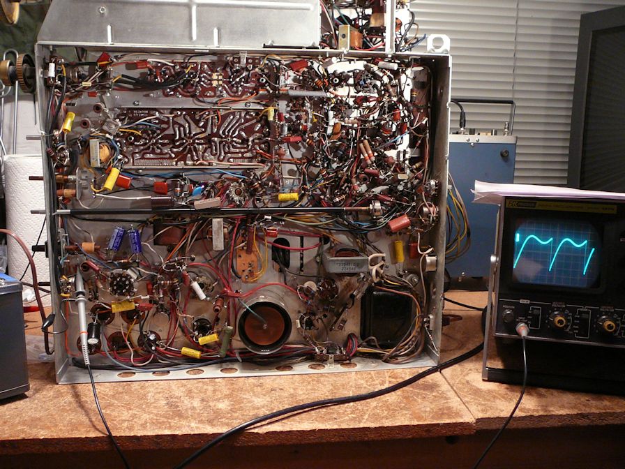 The horizontal has always been rock-solid on this set, so it's disappointing to see it degrade. Subbing oscillator tubes had no effect on voltages or that waveform. I hope I'm not barking up the wrong tree in checking these things. I hope even more that the flyback hasn't failed. Besides checking components around the oscillator, I'll see what I can learn by testing resistances on the flyback. Phil Nelson 
|
|
#2
03-12-2015, 06:36 PM
|
||||
|
||||
|
Here's the schematic showing the horizontal tubes mentioned in my last post.
Phil Nelson 
|
|
#3
03-12-2015, 09:46 PM
|
|||
|
|||
|
Quote:
|
|
#4
03-12-2015, 10:37 PM
|
||||
|
||||
|
Yes, I have a B&K Analyst 1077B that can produce a horizontal grid drive signal.
I assume you mean injecting that signal with the HOT and damper tubes back in place. I will keep a close eye on things and shut down immediately at any sign of trouble. Phil Nelson
|
|
#5
03-13-2015, 01:33 AM
|
||||
|
||||
|
Here is the TV Analyst's horizontal grid drive signal. Very stable.
 I disconnected C115 at its junction with R138/R139 and injected the signal there. With tubes back in place, the screen grid voltage at pin 1-8 dropped from 350V+ to around 125V (160V expected) and the HOT did not red-plate. The voltage at grid pin 4-5 was -75V instead of the expected -38V. Out of curiosity, I reconnected C115 and tried the set without the injected drive signal. The HOT red-plated and I shut down immediately. Which suggests something fishy upstream of the HOT, I guess. This was done on the workbench. I suppose I could set the chassis behind the cabinet and connect to the CRT with this setup, if it's important to look at the screen and judge whether the flyback is still alive. I don't have extension cables for the yoke/convergence/CRT, but the original cables reach if I put the chassis on a big box. It's just hard on the back to crouch down on the floor to measure things  Phil Nelson
|
| Audiokarma |
|
#6
03-13-2015, 10:14 AM
|
|||
|
|||
|
I think you can safely presume the fly is OK and the problem lies entirely in the osc. area. I would concentrate on getting the osc running right as the first order of bizness.
|
|
#7
03-13-2015, 12:42 PM
|
||||
|
||||
|
I will check things around the oscillator tube. The tubular caps and resistors were eliminated long ago. That leaves a handful of mica caps + the various coils.
Phil Nelson
|
 |
| Thread Tools | |
| Display Modes | |
|
|


 Hybrid Mode
