
|
|
|
#151
 04-07-2015, 04:17 PM
|
||||
|
||||
|
Well, I subbed two different 3.58-mc crystals and took care not to overheat their pins.
No change in symptoms. I'm still lacking the negative voltage on pin 6. Still seeing the greenish color bars that disappear when you turn the Color control down. Seems unlikely that all three crystals would be bad, although I guess anything is possible. Phil Nelson 
|
|
#152
04-07-2015, 05:00 PM
|
||||
|
||||
|
I would check or replace C202,
Check or temp remove C209 - check for grid voltage change. What resistance grid to ground...? Check or replace C213. In that little test, no color barbar-pole means no osc. No -10v osc not running. You probably have more than one problem looking at the low signal quality of the burst way back many posts.... .
__________________
Yes you can call me "Squirrel boy" Last edited by Username1; 04-07-2015 at 05:07 PM.
|
|
#153
04-07-2015, 07:15 PM
|
||||
|
||||
|
Replaced C202, C209, C213 -- no change. I even swapped 6AZ8 tubes out of superstition, but no go.
I know the video IF section is not great, so I disconnected that and injected video at the 1st video amp grid. Presumably that is a nice clean signal, although maybe not quite as strong as needed. Phil Nelson
|
|
#154
04-07-2015, 07:36 PM
|
||||
|
||||
|
Quote:
Does that make sense? Terry
|
|
#155
04-07-2015, 08:20 PM
|
||||
|
||||
|
Yes, that makes sense. The tuner is not an issue right now, since I have disconnected the video IF section (and upstream of that, the tuner) to inject a video signal directly at the 1st video amplifier.
When I had things connected normally, I could observe differences when using the fine tuner to tune on either side of the "best" signal, but the TV never displayed anything resembling correct colors. I have done this with various sources -- DVD player, agile modulator, pattern generator, etc. The AGC and color killer appear to be working normally, too. Phil Nelson
|
| Audiokarma |
|
#156
04-07-2015, 08:20 PM
|
|||
|
|||
|
Getting the 3.58 osc running should be the #1 objective, irrespective of whatever other gremlins may still be lurking.
|
|
#157
04-07-2015, 10:21 PM
|
||||
|
||||
|
I'm open to suggestions about how to get that oscillator working. There aren't a lot of other components connected to that tube, other than a couple of ceramic caps and a few resistors.
Phil Nelson
|
|
#158
04-08-2015, 12:49 AM
|
||||
|
||||
|
I wonder if the capacitors in T115 could have gone bad ("silver mica disease" or similar)?
Or, if that transformer was sufficiently mistuned enough, would it kill the oscillator? Maybe, count turns (so you know where you started) and run its slug all the way from end to end and see what you get. I think if you got your scope connected to that circuit's output, you would see quite clearly if/when the oscillator started running. Among the repairs I did on a CTC-4 several years ago, I replaced two 6AZ8s. You already tried that, though.
__________________
Chris Quote from another forum: "(Antique TV collecting) always seemed to me to be a fringe hobby that only weirdos did."
|
|
#159
04-08-2015, 12:58 AM
|
||||
|
||||
|
Here is a 'cover all your bases' suggestion: if you have a 9-pin 'socket-saver/extender' plug it in to the chroma osc. tube socket and see if you have continuity between it and the solder terminals of the socket. Every so often the metal in a socket contact will break in a spot that is hard or impossible to see.
Also if there is a shield on that tube try removing the shield, and seeing if there is an effect on trying to adjust the osc. I've got a CTC-15 that don't won't chroma synch and don't want to oscillate if the osc. shield is on and grounded...So I just removed the shield as a quick fix.
__________________
Tom C. Zenith: The quality stays in EVEN after the name falls off! What I want. --> http://www.videokarma.org/showpost.p...62&postcount=4
|
|
#160
04-08-2015, 06:57 AM
|
||||
|
||||
|
How about those resistors R248, 249, and 250???
R250 should be ok since you got your plate voltage.... Same with primary on T115. Are the voltages on pin 2, and 3 correct....? .
__________________
Yes you can call me "Squirrel boy"
|
| Audiokarma |
|
#161
04-08-2015, 09:39 AM
|
||||
|
||||
|
Quote:
As has been suggested here with your problem, I will next concentrate on insuring the Reactance inductor and circuit are working properly. Closed loops are tough cookies to crack at times! Pete
|
|
#162
04-08-2015, 11:42 AM
|
||||
|
||||
|
Quote:
I will try to follow up on the other suggestions. It would be nice if I could just substitute a 3.58-mc signal, as you could do with a video or horizontal drive signal, but this situation does not seem that simple. Phil Nelson
|
|
#163
04-08-2015, 12:08 PM
|
||||
|
||||
|
Why not try a 3.58 MHZ signal from a signal generator? disconnect the
crystal, feed the signal from the generator to the no-longer oscillator's grid and look on the scope at the two outputs of the output transformer. See what happens if you vary the frequency around 3.58 MHZ (on the scope). Another thing is to check the crystal ... connect the sign generator to it with a 10K resistor and look on the scope. You should see the sharp resonance as you tune. Remember that a previous thread had what was thought to be a bad crystal; they tried two good crystals and they didn't work. It was a bad part. After replacing the bad part but leaving in a "good" crystal it didn't work ... but with the original crystal did. So these circuits are picky about the crystal. If the crystal is bad, it may be that only an exact replacement will work.
|
|
#164
04-08-2015, 12:54 PM
|
||||
|
||||
|
Hey, I just remembered that my Sencore VA62A video analyzer can supply a 3.58-mc drive signal. I hauled it off the shelf and fired it up. My scope has a hard time locking on the signal, but there seems to be a waveform of sorts.
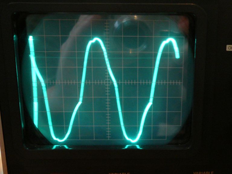 I disconnected the crystal and connected the analyzer's 3.58-mc drive output to pin 6 (grid) of the oscillator tube. After adjusting the generator's output voltage, I began to see rolling colors moving upward on the screen, similar to what I've seen before when the color sync was messed up on my CT-100. 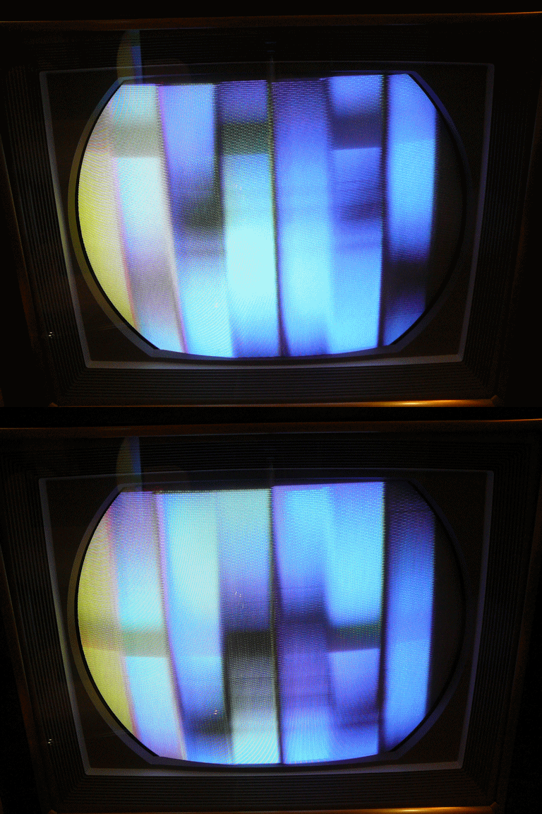 I tried adjusting the reactance coil (L127 in the RCA manual) through its entire range, but this had no effect on the rolling, which never changed speed. And I still don't see normal colors, only rolling patterns against the same green-blue bar background. Turning the TV's Color control had the same effect as before: no change in the colors, and the image will just extinguish if you turn Color down far enough. The symptoms are the same whether I send the color-bar signal from my pattern generator through the TV's tuner and (lousy) video IF sections, or inject video directly at the 1st video amp. I'm going to go back and repeat the procedure outlined on page 22 of the RCA manual, disconnecting the bandpass amplifier, trying to adjust T115, and so on. Phil Nelson Last edited by Phil Nelson; 04-08-2015 at 03:25 PM.
|
|
#165
04-08-2015, 02:21 PM
|
||||
|
||||
|
Its obviously best to use an accurate 3.58, but even the cheesiest signal generator will get close enough to test throughput ... just not phase.
|
| Audiokarma |
 |
| Thread Tools | |
| Display Modes | |
|
|








 Linear Mode

