
|
|
|
#211
 04-22-2015, 02:28 PM
|
||||
|
||||
|
I have ordered a replacement for transformer T115. A while back (post #179), I did a test that seemed to show that T115 is at least partly functional, but I suspect that didn't tell the whole story, and those coils look they overheated in the past.
If the new transformer doesn't improve the situation, I'm not sure what else to try, except to replace the tube socket. I wonder if there's a way to do a bench test of the old transformer after I take it out? Phil Nelson 
|
|
#212
04-22-2015, 09:25 PM
|
||||
|
||||
|
Does it work with the capacitor from the
previous stage and the two outputs of T115 disconnected? I would suggest the next step after checking that is to use the new transformer plus a complete set of new parts, including tube and tube socket, and build a breadboard of the whole thing leaving out the capacitor that connects to the previous stage and leaving the two outputs of T115 disconnected. Run it off any 250-300 v power supply. There is no need for short leads in this circuit, leave them long. You need to get that working and then transfer parts to the main chassis. These oscillators can be picky.
|
|
#213
04-22-2015, 10:51 PM
|
||||
|
||||
|
Quote:
 And then I put the scope on terminal D or F to look for a signal at those points? Phil Nelson Last edited by Phil Nelson; 04-22-2015 at 11:57 PM.
|
|
#214
04-23-2015, 05:57 PM
|
||||
|
||||
|
The new part arrived (the extra can is from my TV).
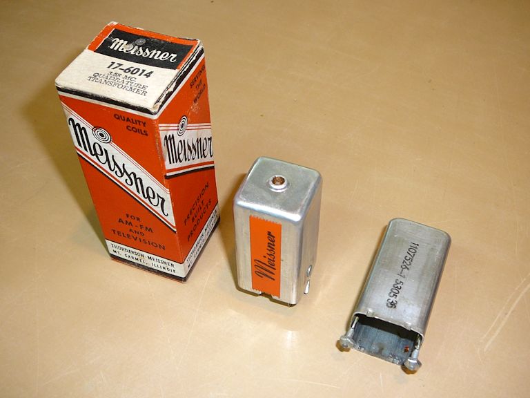 The RCA part number is 100430 and the Meissner part number is 17-6014. I got this from Play Things of Past. I also checked with Moyer; they don't have the Meissner part but they do have a Miller 6025, which is equivalent according to their records. I'm leaving tomorrow morning for another short trip, so I probably won't have time to play with this until next week. Perhaps breadboarding this circuit is not a bad idea. In different schematics, the value of L42 is given as either 11 or 12 muh, and the value of C209 is given as 4, 4.7, or 6.8 pf. I believe I have all the needed parts on hand, except for a ready-made power supply. Maybe I can pull out the power/audio chassis from my Admiral 24C15 B/W set and tap that for B+ and filament voltage. Phil Nelson Last edited by Phil Nelson; 04-23-2015 at 06:40 PM.
|
|
#215
04-23-2015, 09:29 PM
|
|||
|
|||
|
Before doing an external breadboarding, I would maybe try this first.. go ahead and mount the new can and hook up the primary (terms. B & E). Leave the secondaries completely unconnected to minimize loading.
Bring the scope probe close to either L42 or term. B to look for the osc signal. It's amazing that part was still available.
|
| Audiokarma |
|
#216
04-27-2015, 04:34 PM
|
||||
|
||||
|
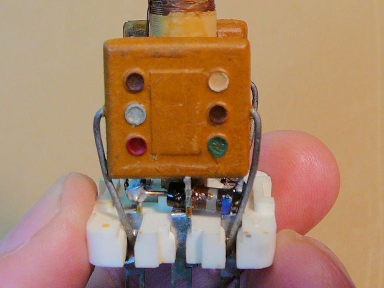
Hmmm. I looked inside the can of the new transformer and discovered a resistor (looks like blue-gray-brown, 680 ohms) in parallel with each cap on the secondary coils:
 The data sheet also shows these resistors: 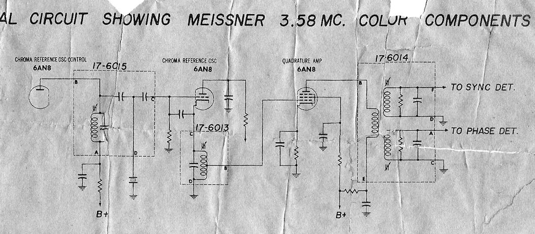 Their "typical" circuit is different than the CTC-4, with a 6AN8 quadrature amp between the reference oscillator and the transformer. It looks like the circuit from the RCA CTC-2B; this schematic specifies the resistors as 680 ohms and the caps as 1500 pf:  The labeling of the secondary terminals is a little different and the resistances differ from the original. I measure 1.7 ohms across the primary (B-E) and .3 ohms across each secondary (F-D and A-C). The original measures 6.8 ohms on the primary and .2 ohms on each secondary. The question is whether this is a good replacement for the CTC-4. I suppose I could just stick it in (noting the labeling differences on the secondaries) and try old_coot88's most recent suggestion . . . . Phil Nelson Last edited by Phil Nelson; 04-27-2015 at 06:30 PM.
|
|
#217
04-27-2015, 07:11 PM
|
||||
|
||||
|
Ain't those caps plactic molded paper type?
__________________
Tom C. Zenith: The quality stays in EVEN after the name falls off! What I want. --> http://www.videokarma.org/showpost.p...62&postcount=4
|
|
#218
04-27-2015, 08:48 PM
|
||||
|
||||
|
They look like good old-fashioned "postage stamp" style micas to me. The little resistor is tucked under the cap.
Phil Nelson
|
|
#220
04-27-2015, 10:09 PM
|
||||
|
||||
|
I hate these danged dot schemes, but according to this cheat sheet, the upper right (in that photo) dot would be silver if it's molded paper; a white dot indicates mica:
http://www.tpub.com/neets/book2/3g.htm As for the rest, brown-green-red means 1500, silver means 10% tolerance, and the last brown means who knows what. There's a little point on the green dot showing which direction to read. The caps are stamped El-Menco on the back, which tells me nothing, since E-M made all sorts of caps, including mica and molded paper. Phil Nelson
|
| Audiokarma |
|
#221
04-27-2015, 10:53 PM
|
||||
|
||||
|
I could swear I've seen some domino cap charts that list white as paper...
The physical size, look and value (.0015uF) all scream paper cap to me.
__________________
Tom C. Zenith: The quality stays in EVEN after the name falls off! What I want. --> http://www.videokarma.org/showpost.p...62&postcount=4
|
|
#222
04-28-2015, 11:53 AM
|
||||
|
||||
|
I disconnected one lead of the cap for testing.
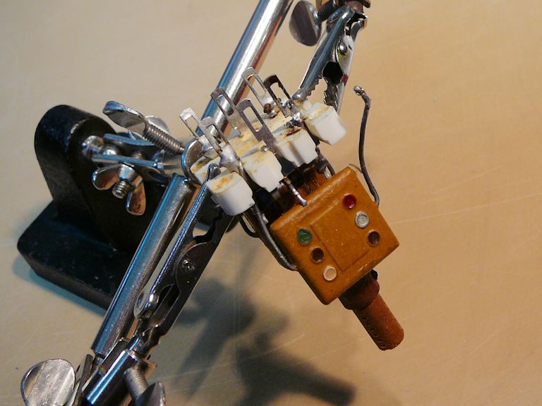 It's a little hard to see in the glare, but the eye tube's shadow is fully open, showing no leakage under 450 volts, using a new 1500-pf mica as a comparator. 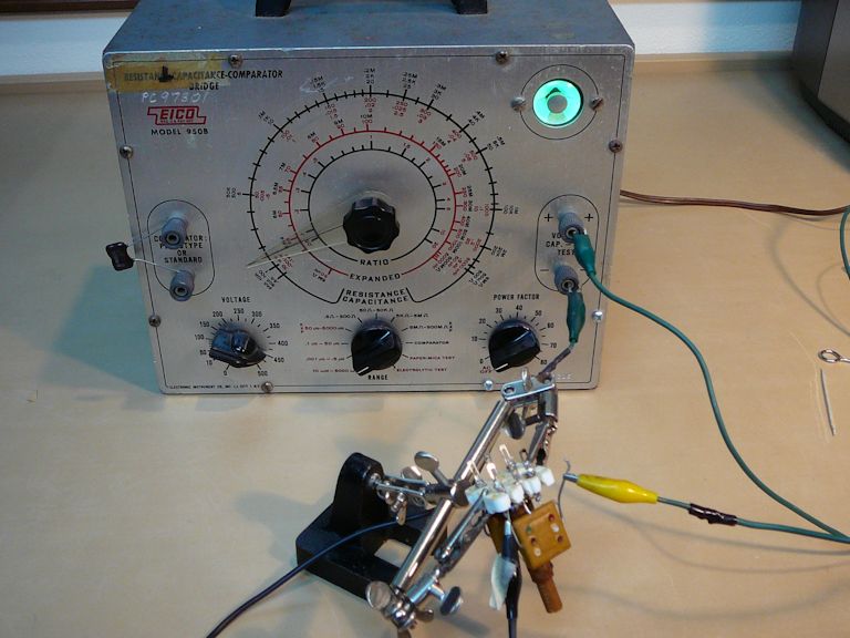 I guess I will call this cap C290 after the CTC-2B schematic. Whatever it's made of, I'm calling it good enough for this application. Now the trick will be to install it without torching everything else in the neighborhood, including parts I previously replaced.  Maybe I will install all new components and leads on the transformer first, slip the pre-wired assembly through the hole, and then connect up. Phil Nelson Last edited by Phil Nelson; 04-28-2015 at 12:30 PM.
|
|
#224
04-28-2015, 01:25 PM
|
||||
|
||||
|
Quote:
Cheers,
__________________
Brian USN RET 22YRS (Avionics/Cal) CET-Consumer Repair and Avionics ('88) "Capacitor Cosmetologist since '79" When fuses go to work, they quit! Last edited by Findm-Keepm; 09-29-2017 at 06:38 PM.
|
|
#225
04-28-2015, 02:03 PM
|
||||
|
||||
|
Mica or Paper issue aside... Is that even the correct transformer... looks like it is configured the same as L-45, the quadrature transformer in the CT 100. Might be good to "breadboard" the circuit first to see if it will indeed oscillate without the buffer amp.
 jr Last edited by jr_tech; 04-28-2015 at 02:17 PM.
|
| Audiokarma |
 |
| Thread Tools | |
| Display Modes | |
|
|


 Linear Mode

