
|
|
|
#226
 04-28-2015, 03:08 PM
|
||||
|
||||
|
Yes, that was my question -- should this xfmr work at all, given its component differences and the circuit differences between the earlier sets and the CTC-4? (The CT-100 has the same circuitry shown in the CTC-2B snippet I included a few posts ago.)
I sent a follow-up email to Moyer asking if they happen to have a data sheet for the Miller 6025 xfmr, which purported to be a match. They emailed me a scan of the data sheet, showing that the Miller xfmr is a match for the Meissner part -- not the CTC-4. One way or another, I guess I'm destined to take the old transformer out. If breadboarding the new one doesn't work, then the last resort may be trying to rewind the original. But I could try the original in the breadboard circuit before attempting a rewind. I have these parts on hand. Is this what we're talking about building?  I'm hoping I can tap the 6.3VAC filament supply and B+ supply from the power/audio chassis of my Admiral 24C15 B/W set. Phil Nelson Last edited by Phil Nelson; 04-28-2015 at 03:51 PM. 
|
|
#227
04-28-2015, 06:29 PM
|
|||
|
|||
|
Phil, there's something I was gonna suggest earlier to see if the osc can be coaxed to run, but thought the better of it until seeing the CTC-2 schematic. The CTC-2 has the osc plate clamped hard with a .01 cap.
Try disconnecting the CW xfmr's primary completely, and shunt directly across where the primary was. Bypass cap C211 is now clamped directly to the plate. This duplicates how the CTC-2 osc plate is wired. Bring the scope probe next to L42 to see if the osc is running. -- If not, maybe try a few higher values for R250 up to 39K to see if it makes any difference. -- If still no go, maybe there's a conductive track inside the tube socket itself. Most likely lugs 3 and 6 (cathode and G1). If you disconnect those two lugs (no tube in socket), they should show infinite resistance to ground, verifying no conductive path. Then (with lugs 3 and 6 still floating) power up and see that there's no positive voltage on them, verifying no leakage path from G2 or plate lugs. If the socket shows good, I dunno what else would be revealed by breadboarding. But what the heck... Last edited by old_coot88; 04-28-2015 at 10:07 PM.
|
|
#228
04-28-2015, 08:54 PM
|
||||
|
||||
|
Quote:
Quote:
Phil Nelson
|
|
#229
04-28-2015, 08:58 PM
|
|||
|
|||
|
maybe I am missing something here but is that just a amplifier that is tuned for the horz rate? maybe the issue is the tube before it? I see a cap coupling a signal to the control grid, does not look like a correction voltage but more like the signal to drive the tube.
|
|
#230
04-28-2015, 10:03 PM
|
|||
|
|||
|
Quote:
-- Quote:
|
| Audiokarma |
|
#231
04-28-2015, 10:05 PM
|
|||
|
|||
|
Quote:
|
|
#232
04-28-2015, 10:14 PM
|
||||
|
||||
|
Quote:
 If I supply a color bar signal at the video amp and slow down the sweep rate, I see a more complex waveform; the amplitude of this one goes down if I turn down the Color control.  Not sure if the second trace proves anything, but it was interesting to look at. Incidentally, with nothing connected to the primary (terminals B-E), it still measures 6.8 ohms as given in the Sams manual. Phil Nelson Last edited by Phil Nelson; 04-28-2015 at 10:30 PM.
|
|
#233
04-28-2015, 10:39 PM
|
|||
|
|||
|
Quote:
 What's the actual p-p amplitude of that? What's the actual p-p amplitude of that?Looks like the thing is actually running. OK (assumimg you haven't unmounted the old CW xfmr yet), just take the new one and connect its primary in place of the old one, using a couple of short leads (after removing that jumper). See if the osc still runs. Last edited by old_coot88; 04-28-2015 at 10:53 PM.
|
|
#234
04-28-2015, 11:34 PM
|
||||
|
||||
|
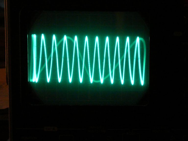
Maybe this photo will give a better idea what I'm seeing. My scope has a lot of trouble locking onto the signal -- hope it's not a phantom.
 Edit: I just connected the primary of the new transformer in place of the old one (i.e., B connected to pin 1 and E connected to junction of R250/CC211. I get the same waveform, whose amplitude collapses if I temporarily disconnect the primary. Phil Nelson Last edited by Phil Nelson; 04-29-2015 at 12:38 AM.
|
|
#235
04-29-2015, 12:35 AM
|
|||
|
|||
|
Quote:
- But the question remains, with the new xfmr's differences, will it deliver correct phasing, amplitude etc downstream? - Also, is the osc running with the new L42 or the old one? Last edited by old_coot88; 04-29-2015 at 02:14 AM.
|
| Audiokarma |
|
#237
04-29-2015, 01:14 AM
|
||||
|
||||
|
Let's try this again. The scope is on channel B with the vertical set at 2 volts/cm. The sweep time is set at .5 us/calibrate, and I pulled out the 5x mag knob.
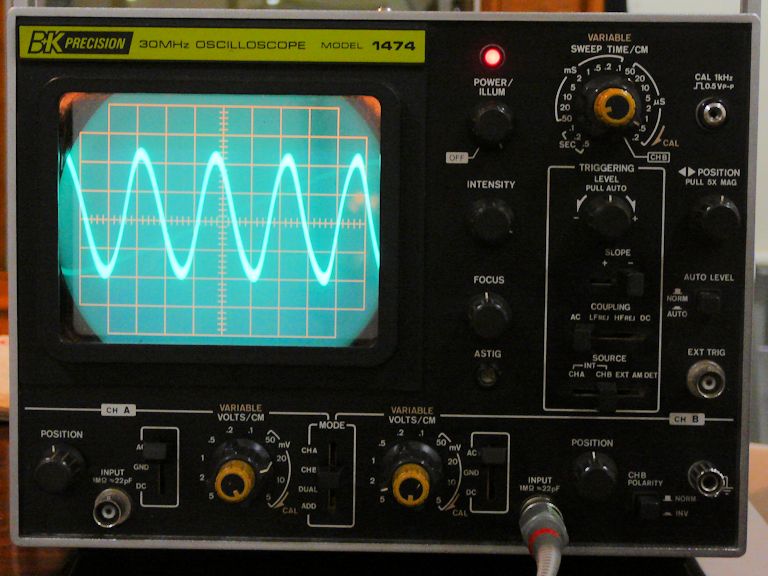 I scrounged up my digital SW receiver and got a nice clear tone at 3586 kilohertz when I held the antenna near L42. The tone disappeared when I turned off the TV. I do have a frequency counter somewhere out in the garage, but I don't trust its accuracy more than the digital radio. The oscillator is running with the new L42. It's running with new everything, except for the tube socket and the quadrature transformer. If the oscillator is indeed running, that feels like progress. Time to call it a night; I can try some more things tomorrow. Phil Nelson
|
|
#238
04-29-2015, 01:53 AM
|
|||
|
|||
|
I'd say the tube socket is fine, provided there's no intermittency when you wiggle the tube.
- If you end up using the new CW xfmr, it'd be a good idea to clip out those two resistors before installing it. That way, if the resistors are actually needed, they can be placed externally. - If it's the primary bad in the old xfmr, it may be re-windable using roughly the same gauge wire and same number of turns. The primary is untuned, serving only as coupler or 'tickler' to the secondaries, so its exact inductance is not critical. Last edited by old_coot88; 04-29-2015 at 02:16 AM.
|
|
#239
04-29-2015, 01:57 PM
|
||||
|
||||
|
When I reconnect the old quadrature transformer (still in place and connected to everything else), the 3.58-mc waveform is visible and I hear a tone WHEN there is no signal to the receiver.
 When I turn on the color bar generator to inject a signal at the 1st video amp, the waveform is flatlined.  I guess the oscillator is capable of running, but something else is killing (or swamping out?) the oscillation when a video signal is present. For what it's worth, I reviewed my notes of voltage readings in the color circuits. I found wrong voltages on the grids (pins 2 and 7) of V125, the 12BH7, R-Y/G-Y demodulator tube, measuring near zero when those grids should have around -20V (or around -15V according to Sams). At the time I attributed this to the oscillator not running, since the outputs of T115 connect to those grids, but who knows? Another anomaly at V121B, the 6AZ8 bandpass amp, where the grid should have about -12V and I measured only about -3V or less. I haven't forgotten the toasted appearance of the old transformer. Phil Nelson Last edited by Phil Nelson; 04-29-2015 at 02:50 PM.
|
|
#240
04-29-2015, 02:45 PM
|
|||
|
|||
 So the osc runs now with the old T115 in place but wouldn't before. So the osc runs now with the old T115 in place but wouldn't before. What happens if you disconnect C202 (thus severing the osc from everything 'upstream')? Does it still run? If so, is there any sign of color barberpoling when you inject signal? What happens if you disconnect C202 (thus severing the osc from everything 'upstream')? Does it still run? If so, is there any sign of color barberpoling when you inject signal?
|
| Audiokarma |
 |
| Thread Tools | |
| Display Modes | |
|
|


 Linear Mode

