
|
|
|
|
|
#1
 04-29-2015, 03:59 PM
|
||||
|
||||
|
Related to the burst keyer, I never got as far as trying the AFC adjustment procedure listed on page 23 of the RCA service clinic manual (specifically, adjusting T112, the phase detector transformer, or R228, the AFC balance control, which affect the keyer output). Pages 46-48 have more info.
Is it OK to use my digital multimeter for voltage measurements in those procedures, or will it load down the circuits too much? I don't have much faith in my old RCA Voltohmyst, but I could try using the scope for voltage measurements instead. Phil Nelson 
|
|
#2
04-29-2015, 05:15 PM
|
|||
|
|||
|
Wonder if you coulda cleared a tin whisker or something in the old T115 whilst removing and reinstalling it.
 Now that you got barberpoling, try reconnecting C202, and go back further and disconnect R242. If still barberpoling, you should be able to zero beat the osc using the reactance coil, though it won't have any sync. (Digital meters supposedly are high impedance like a VTVM, so shouldn't cause any loading problem.)
|
|
#3
04-29-2015, 05:30 PM
|
|||
|
|||
|
I would be tempted to scope and look for clean burst to be coming from the keyer. It like the osc free runs, but adding the control kills it, so maybe the control is not really a nice clean burst, but some video getting in there.
|
|
#4
04-29-2015, 06:18 PM
|
||||
|
||||
|
I reconnected C202 and disconnected R242. With no signal at the receiver, the waveform at L42 looks like the following and I hear buzzing instead of a clear tone from my SW radio tuned to 3586 KHz:
 When I turn on the color bar generator, the waveform changes to this, and I see the same old green bars on the screen (no barberpoling). Louder buzzing from the SW radio:  Quote:
Edit: Well, I'll be hornswoggled. I reconnected both C202 and R242 in preparation for scoping the burst keyer. (Everything is now reconnected, in other words.) To my surprise, I saw rolling color bars, which I can make to hover in place by adjusting the reactance coil (L127). 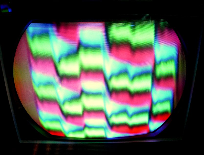 ?? Phil Nelson Last edited by Phil Nelson; 04-29-2015 at 06:50 PM.
|
|
#5
04-29-2015, 06:50 PM
|
|||
|
|||
|
Dang, it's almost as if a B+ line is not being bypassed adequately and has got a bunch of junk riding on it. Try scoping some B+ points and see if there's any unusual stuff on it (other than normal low level power supply ripple).
|
| Audiokarma |
|
#6
04-29-2015, 07:42 PM
|
||||
|
||||
|
Not sure if I'm doing this right, but here is the +285V line at the junction of R249/R250 near the 3.58 oscillator tube, with no signal at the receiver:
 When I turn on the color bar generator, the trace changes to this:  The traces are somewhat cleaner than what appears in the photos; both of them bounce up and down a bit on my scope. I got similar results when scoping that line at its origin (junction of R266/C117B in the p-s) and at pin 2 of V117, the horizontal oscillator. Phil Nelson Last edited by Phil Nelson; 04-29-2015 at 08:02 PM.
|
 |
| Thread Tools | |
| Display Modes | |
|
|


 Hybrid Mode
