
|
|
|
|
|
#2
 04-29-2015, 09:32 PM
|
||||
|
||||
|
I unsoldered C204 and tested it on my EICO 950B cap checker, and it is fine. I also disconnected the line that I was using to inject a video signal, in case that was introducing noise.
With the IF reconnected and a signal coming in through the antenna, I can see rolling color bars when using a color bar pattern. I was never able to see them before with the IF connected, only the static "colorless bars." The waveform at L42 is still clean and stable, so I conclude the oscillator is definitely running. Tomorrow is another day . . . . Phil Nelson 
|
|
#3
05-01-2015, 01:19 AM
|
||||
|
||||
|
Maybe there's hope for the old girl yet.
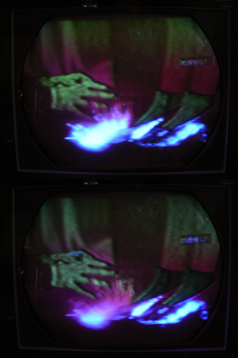
 (Ignore the dark horizontal band, which is a camera artifact.) Today I went on a resistor hunt, checking every resistor in the color signal path, starting at the point where the video signal is picked off from the IF section and working through everything but the demodulators. I replaced a number of resistors that were out of spec. Then I powered up the set mainly to confirm that I hadn't made things worse. I also wanted to scope the outputs of the quadrature transformer to see if anything like a signal could make it out that way. After several scope photos and a few adjustments, I was surprised to see real color bars for the first time on this TV. Yes, I know the colors in that pattern are incorrect. There's obviously a lot more work to do, but it's nice to see a little improvement. I'll finish the resistor hunt tomorrow or Saturday. Phil Nelson
|
|
#4
05-01-2015, 08:51 AM
|
||||
|
||||
|
Bravo!! That must be very satisfying. That set has proven to be a tough dog and I bet you're learning a lot from it. I'm sure it won't be long now before we see a gorgeous screen shot of Dorothy
 -Clark
|
|
#5
05-01-2015, 10:21 AM
|
|||
|
|||
|
Great work Phil! (Looking for a clapping-hand smiley)
 What does some reglar programming look like on it at this point? What does some reglar programming look like on it at this point?
|
| Audiokarma |
|
#6
05-01-2015, 12:05 PM
|
||||
|
||||
|
Quote:
 After I finish the resistor hunt, I will do some more voltage checks and look at the color AFC alignment procedure and other adjustments. By the way, here are the outputs from T115, the quadrature transformer. First is terminal D, which goes to the G-Y demodulator grid. Nice and regular:  Here's the output at terminal F, which goes to the 6AL5 phase detector (V120) and to the R-Y demodulator grid. Similar amplitude, but not the same pretty sine wave:  Phil Nelson Last edited by Phil Nelson; 05-01-2015 at 12:12 PM.
|
|
#7
05-13-2015, 01:36 PM
|
||||
|
||||
|
I'm debating where to go next. I have replaced a number of marginal resistors, without any dramatic improvements. When injecting a video signal, I am able to get stable color bars (with wrong hues) by working through the entire color AFC alignment procedure on page 22 of the RCA service clinic manual.
However, in step 3, I am not able to find a voltage peak when turning the bottom adjuster of quadrature transformer T115. The voltage increases in one direction until the adjuster hits the wall. And I am still getting only zero volts on pin 6 of the chroma reference oscillator (V124A) rather than the desired -10 volts. Likewise with adjusting T112 (bottom) in step 6: I don't find a peak -- the voltage increases in one direction until the adjuster stops. My sense is that the color AFC system just BARELY works at all, and only with a very strong color bar signal from a generator. When I switch to normal program content, things fall apart. The colors are all wrong and the image is poorly focused. I have a replacement transformer, but it's not identical to the original. Instead of a 1000-pf cap in parallel with each secondary coil, it has a 1500-pf cap paralleled by a 680-ohm resistor. Maybe it's a plug-in-play replacement, maybe not. Its example circuit is taken from the RCA CTC-2B, which uses an amp between the oscillator and the transformer. I'm debating two options: 1. Just stick in the new transformer and see what happens. (Pro: maybe it'll work. Con: the replacement is not easy, and if I wreck either the old or new transformer in the process, I'm worse off than before.) 2. Breadboard the CTC-4 oscillator circuit using the new transformer. (Pro: if it works in the CTC-4 circuit without modification, then we're home free. Con: if it doesn't work, then I'm torn between modifying the new transformer or trying to rewind the old one, and if neither of those options works, then I have a completely dead TV.) Since I don't have standalone power supplies, perhaps I could power the breadboard circuit by tapping into the CTC-4's 6.3VAC filament circuit and +285VDC B+ circuit. It needs about -10VDC bias voltage; perhaps I could tap into the CTC-4's -20VDC supply and shunt some of that to ground with a pot. Or, I could throw a tarp over it and work on something else, but it bugs me to leave the TV in this half-baked condition. Edit: re breadboarding, I have an additional concern, which oldcoot_88 alluded to earlier, that it might seem to work on the workbench -- that is, the oscillate might oscillate and the transformer might pass a signal -- but the output might not be right in phasing & amplitude for the CTC-4. Phil Nelson Last edited by Phil Nelson; 05-13-2015 at 01:53 PM.
|
 |
| Thread Tools | |
| Display Modes | |
|
|


 Hybrid Mode
