
|
|
|
|
|
#1
 05-14-2015, 06:22 PM
|
||||
|
||||
|
Given the construction, I don't know why the outputs shouldn't produce the same waveform. I'm not a transformer designer, though.
Yes, that's a YB 400. Phil Nelson 
|
|
#2
05-14-2015, 10:16 PM
|
|||
|
|||
|
Could you post some more of the schematic directly downstream of T115? Just curious what it's loading into.
|
|
#3
05-15-2015, 12:48 AM
|
||||
|
||||
|
Here's the whole schematic in four parts:
http://antiqueradio.org/art/RCACTC-4SchematicPart1.jpg http://antiqueradio.org/art/RCACTC-4SchematicPart2.jpg http://antiqueradio.org/art/RCACTC-4SchematicPart3.jpg http://antiqueradio.org/art/RCACTC-4SchematicPart4.jpg The bit you're looking for is in Part 3. In a nutshell, the outputs from T115 go to the grids of the R-Y and G-Y demodulators (V125). One of them also goes to the chroma phase detector (V120). Phil Nelson
|
|
#4
05-17-2015, 07:11 PM
|
||||
|
||||
|
While messing around with the breadboard circuit, it occurred to me to use the scope to look at the phase relationship of the outputs from the quadrature transformer. I was able to adjust the transformer so that they were 90 degrees out of phase, but one output was still lumpy. Perhaps not surprising, considering that the breadboard circuit was crudely built, hanging off the chassis by various foot-long leads.
I disconnected the breadboard circuit, replaced a couple more resistors around the R-Y/G-Y demodulator, and reconnected everything with the old T115 transformer in place. I also dug up a second scope probe so that I could view both outputs at once. Whaddya know, both outputs are nice sine waves! Using the top and bottom adjusters on T115, I got them into a 90-degree phase relationship: 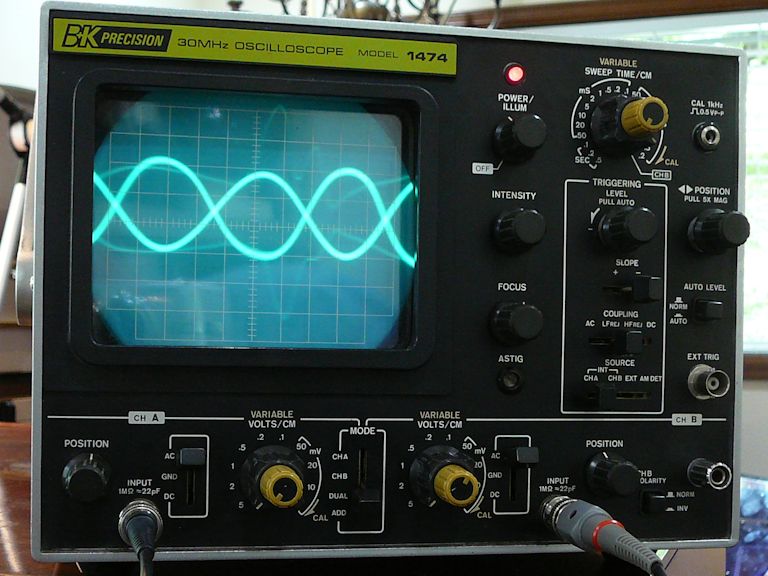 By switching the time base to channel B, I was able to get a purty-good 90-degree circle, as described in my scope manual: 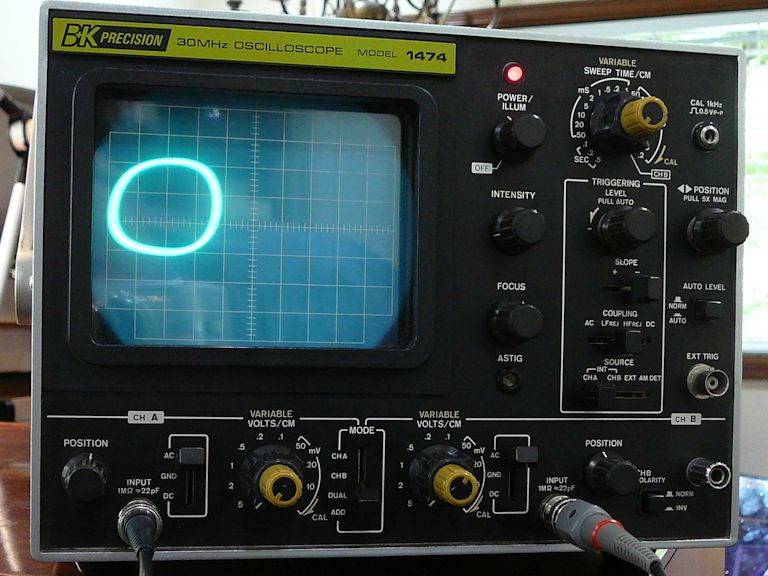  This was all done without reference to other circuits or to what appeared on the screen. When I looked at the screen, I saw these color bands, which can be made to stand still:  Not a correct picture, but my goal here was to confirm that: -- The chroma oscillator works. -- The quadrature transformer passes the 3.58-MHz signal. -- The transformer adjusters affect the phase relationship of its outputs. If these things are indeed working correctly, I'll cross 'em off the list and look elsewhere for solutions. Phil Nelson Last edited by Phil Nelson; 05-17-2015 at 08:43 PM.
|
|
#5
05-17-2015, 09:19 PM
|
|||
|
|||
|
Looks like the 3.58 osc is quite a bit off freq. The reactance coil adj should be able to bring it back.
|
| Audiokarma |
|
#6
05-17-2015, 11:36 PM
|
||||
|
||||
|
Hmm, adjusting the reactance coil doesn't really improve things. The speed of the rolling horizontal bars changes as I adjust either way, but it hits the end of its travel.
I can look at it some more tomorrow. Phil Nelson
|
|
#7
05-18-2015, 12:42 AM
|
|||
|
|||
|
Is the readout on that radio accurate enuff to tell if the osc is running above, or below 3.58?
The value of that 270pf cap (C213) in the resonant tank could be altered a little bit up or down, depending on which way it needs to go. 10 pf might be a good starting figure.
|
|
#8
05-20-2015, 12:16 PM
|
|||
|
|||
|
Phil,
Since you've already done the alignment procedure per the manual, presumably the tint ('hue') control shows some evidence of working when you turn it. - The display looks like possibly one of the two demods is really wonky or maybe not working at all. Assuming the hue control is working, I would try this.. using a cap of .01 - .047 or thereabouts, short out each of the demods in turn, watching to see what the tint control does while one demod is shorted. - At the 12BH7 demod tube V125A, short the plate (pin 1) to ground*. This kills the R-Y signal. On a normally working set, the display will show some colors missing, but with the tint control still functional. Now short the plate of the other (G-Y) channel (pin 6). You should get a different set of colors, and the tint control should still work. - If either channel shows little or no color, and/or the tint control has little or no effect, I would look further into that channel for the problem. - Of course if both channels pass the test, then the wonky-color fault lies somewhere else. - *Or to B+, doesn't matter since it's signal ground. Last edited by old_coot88; 05-20-2015 at 12:20 PM.
|
|
#9
05-20-2015, 02:27 PM
|
||||
|
||||
|
Thanks, that gives me some things to try. I haven't redone the alignment procedure since the latest replacements (which included a couple of resistors on the demodulators).
The tint (hue) control does have an effect. Colors shift around in the bars, but they are never correct. Edit: I still haven't done the alignment, but here are quick photos showing the results of shorting the demodulators. 1. Demodulators normal (nothing shorted). Wrong colors, of course:  2. Demodulator pin 1 shorted:  3. Demodulator pin 6 shorted:  The tint control affects colors in both cases. Gotta run some errands, but I can return to it this evening. Phil Nelson Last edited by Phil Nelson; 05-20-2015 at 04:25 PM.
|
|
#10
05-20-2015, 04:13 PM
|
|||
|
|||
|
On second thought, before doing anything else, check for proper voltages on the 6AG7 demod driver tube V123. If good, check xfmr T114 for continuity on the secondary.
If good, scope the signal coming out of terminals A and D of T114. That's the 3.58 bandpass signal before it's mixed with the 3.58 osc. signal.
|
| Audiokarma |
 |
| Thread Tools | |
| Display Modes | |
|
|


 Hybrid Mode
