
|
|
|
#1
 06-10-2015, 04:35 PM
|
||||
|
||||
|
CTC-7... What to expect?
Hello all!
I just scored a free CTC-7 in the pensbury cabinet off of the classifieds here... From what I have seen the set has a raster and horizontal and vertical deflection (needs to be adjusted) and the colors are off but other than that from just a brief overview everything looks pretty good electrically.... Of course, I will recap everything just for good measure. But only having restored two b&w sets (RCA 8-PT-7032T and 8-PT-7012) this ctc will be my first color set. What should I expect? Anything particularly difficult about restoring this set? Last edited by SwizzyMan; 06-10-2015 at 05:35 PM. 
|
|
#3
06-10-2015, 05:30 PM
|
||||
|
||||
|
Quote:
|
|
#6
06-10-2015, 05:42 PM
|
||||
|
||||
|
Quote:
|
|
#7
06-10-2015, 05:48 PM
|
||||
|
||||
|
Video amplifier area has always been a problem for me on these- runs so hot it burns the PCB to a crisp. Best to elevate it with a socket saver. Also, there is usually one bumblebee capacitor in these across the sine wave coil on the horizontal oscillator board. If you change only ONE cap in this set- change that one. It's bad. Causes horizontal frequency drift and poor/no hold lock.
|
|
#8
06-10-2015, 09:31 PM
|
|||
|
|||
|
what to expect
https://www.youtube.com/watch?v=rWXbAD5eSGI https://www.youtube.com/watch?v=d05VbgDtI_c https://www.youtube.com/watch?v=2wYn3xLrZj0 https://www.youtube.com/watch?v=lJUeUH8bTW4 The second video is prob the best it covers a lot on caps and other issues. Last edited by DaveWM; 06-10-2015 at 09:43 PM.
|
|
#9
06-11-2015, 10:45 AM
|
|||
|
|||
|
if you are new to pcb work, be warned, these are very early pcb and do not take well to rough handling. You want to use a 25watt or so soldering iron (never a gun) and I find solder wick very helpful to remove excess solder. The upside is its hard to goof with wiring since you just remove and replace one at a time on pcb. I generally go with higher voltage ratings as they often fit better (old cap were quite large in comparison to new stuff).
The point to point wiring esp around the chroma is pretty tight at times. I suggest you use the utmost care when dealing with that part. Its easy to brake off tabs from the tube sockets, coils, etc.. from too much heat and rough handling. It is for that reason that I generally pig tail the connections choosing not to try and remove the old wires from the delicate tabs. This is esp true when you have several thick wire parts solder to a singe hard to get at tube socket. I know some folks frown on pig tails but done well they work fine, just make sure the old wire is clean so the solder will wick into the joint, just like any other solder joint.
|
|
#10
06-11-2015, 02:17 PM
|
||||
|
||||
|
Here are some restoration notes that you may find helpful:
http://antiqueradio.org/RCACTC-7ColorTelevision.htm My CTC-7 is a Pensbury, the same model as yours. As you can read in that article, I replaced the electrolytics, along with bumblebee and "maroon drop" mylar caps on the PC boards. That gave me a very nice picture. At that stage, it seemed stable and reliable (knock on wood), so I haven't messed with anything else. So, I would start with a basic recap and then step back and see how it performs. Do voltage checks at that point to satisfy yourself that you can play it without one hand trembling on the power cord in case smoke billows out the back. If the colors look natural to your eye, I would not mess with color adjustments other than operating the user controls in front. If the TV already has good convergence, etc., you may be better off leaving that stuff alone, at least for now. Just my $0.02. Phil Nelson Phil's Old Radios http://antiqueradio.org/index.html
|
| Audiokarma |
|
#11
06-11-2015, 05:02 PM
|
||||
|
||||
|
Quote:
|
|
#12
06-11-2015, 06:05 PM
|
||||
|
||||
|
For any old PCB tube set BE GENTILE ! Things get very crispy.
It gets so bad at times neither the part or etch take solder. Socket savers a great idea where there has been a lot of heat. Also a muffin fan is nice to suck the heat out. When recapping or shotgunning do just a few at a time then run the set. Be sure its OK & make note of any major changes such as " C249 vert size much larger, adjusts normal". Disc caps almost never go bad. Dont change unless burned or cracked. Finally if you need to pull off the CRT socket slowly pry it off with a little screwdriver while holding the plastic part at the CRT end. I doubt many of these still have glue & you can kill the CRT. Good luck ! 73 Zeno 
|
|
#13
06-11-2015, 06:24 PM
|
||||
|
||||
|
Quote:
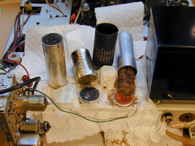 The two on the left might have worked. At least, the electrolytic paste inside them might still be somewhat operational. The one on the right is totally dried up, crumbling, and shrunken -- like a fossil. The insides are garbage. If I had powered up the set without monitoring the current draw, etc., and that cap was shorted, I might have burned up the power transformer. It's risky to leave them in place without at least doing some testing. For some people, testing means turning the TV on and holding your hand on the can to see if it burns you. A slightly more scientific way is to monitor the amount of current drawn by the TV and pull the plug if it spikes above what is normal. You can also disconnect those capacitors and test them individually under the right voltage, or even try to "re-form" them by gradually increasing the voltage and carefully monitoring current. In my experience, even electrolytics that appear to "re-form" after a while, may not be reliable for indefinite service. They may fail at any time without warning, and possibly cause damage when they go bye-bye. I often replace all of the electrolytics because then I am sure they'll be reliable, and I don't have to sit around wondering if my TV is going to go up in smoke. Other people like to re-use every old electrolytic if humanly possible; they understand the risk and don't mind taking it. Only you can decide how much risk you can tolerate and how you intend to use the TV. If it's going to be a "daily driver," you may want to err on the side of caution. If it's something you'll only play for a few minutes a couple of times a year, to show off to guests, maybe leaving the old electrolytics alone isn't such a big deal. Phil Nelson
|
|
#14
06-11-2015, 06:51 PM
|
||||
|
||||
|
My CTC-7 came to life when I resoldered the ground stakes on each of the PCB's.
__________________
Bruce
|
|
#15
06-11-2015, 07:37 PM
|
||||
|
||||
|
Quote:
comes on and works, you have run it for a few hours and it's ok, then you may want to slowly replace parts. Replacing stuff that explodes, causes smoke, or burns out stuff that can't be replaced is a good idea..... Start with power supply capacitors, work your way to all electrolytics.... Eventually you can replace most of the caps, people here have lists of types of caps in specific sets that almost always will fail, do them. But keep in mind there are many many posts here that begin "I recapped my set and now......" Wiring mistakes, worse new parts choices than the originals, etc.... Best idea is to do the power supply, then make sure the set works. Do some other section, then make sure the set works.... etc.... And when yer done, remember there will be a buncha stuff you can't replace cause it just ain't available.... With a 1969ish kinda cutoff, most stuff earlier than that should have the electrolytics replaced, there are some safety caps in later sets that are known trouble, but earlier stuff, 1950's 1940's age is working against ya- There is too much of a chance of bad failure.... You should have fun, and be careful.
__________________
Yes you can call me "Squirrel boy"
|
| Audiokarma |
 |
| Thread Tools | |
| Display Modes | |
|
|


 Linear Mode

