
|
|
|
|
|
#1
 07-17-2015, 09:40 PM
|
||||
|
||||
|
Quote:
__________________
Tom C. Zenith: The quality stays in EVEN after the name falls off! What I want. --> http://www.videokarma.org/showpost.p...62&postcount=4 
|
|
#2
07-19-2015, 12:47 PM
|
||||
|
||||
|
Quote:
Phil Nelson
|
|
#3
07-20-2015, 11:02 PM
|
||||
|
||||
|
Okay, here are the key video preamp parts. From left to right, we have three Miller TV-151 4.5-MHz sound traps, a Miller 6195, and a Miller 4566:
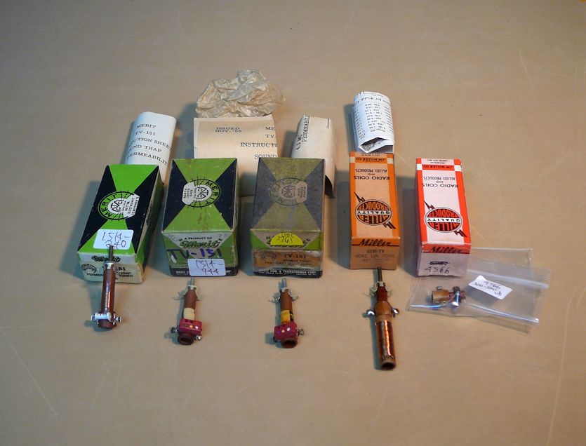 There are minor differences among the three TV-151s, but presumably they work the same. The last two are adjustable across the target value of 400 muh given for L3 in the schematic; I'm hoping that one or the other will work. Tomorrow I'll gather the other components and start building. Phil Nelson Phil's Old Radios http://antiqueradio.org/index.html
|
|
#4
07-28-2015, 11:57 AM
|
||||
|
||||
|
Quote:
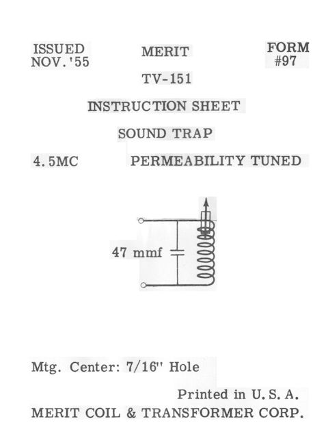 The sheet identifies that as a 47-mmf cap. Two of my traps have a 47-mmf cap and the third has a 45-mmf cap. They all measure 2.2 ohms across the coil: 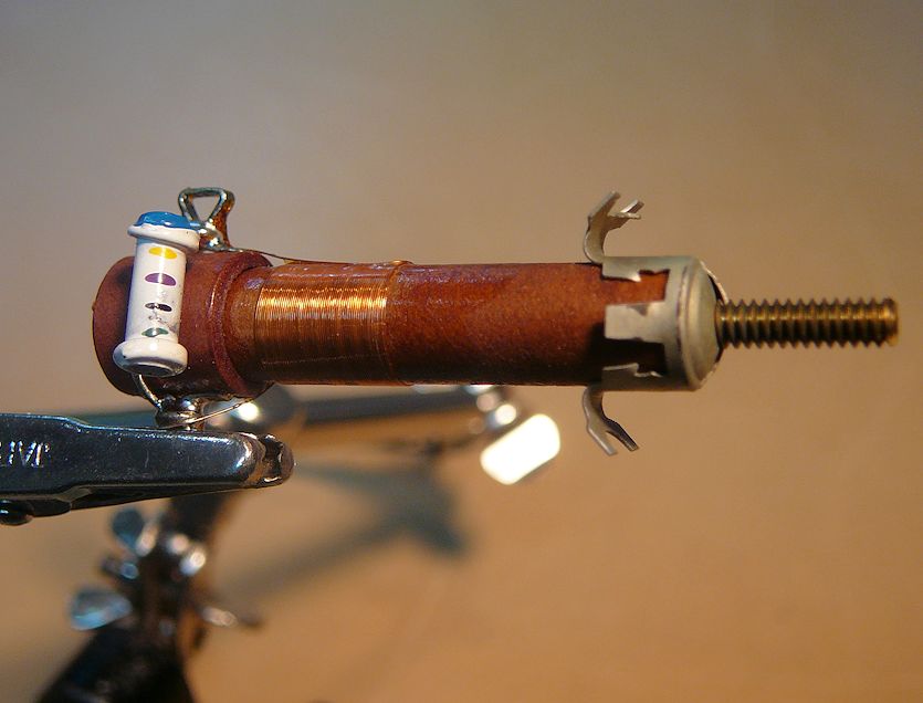 I put one of them on a scope with a 4.5-MHz signal and was able to peak the amplitude by turning the adjuster. I don't know if that's where you want the adjustment to be in the preamp, but I was curious. 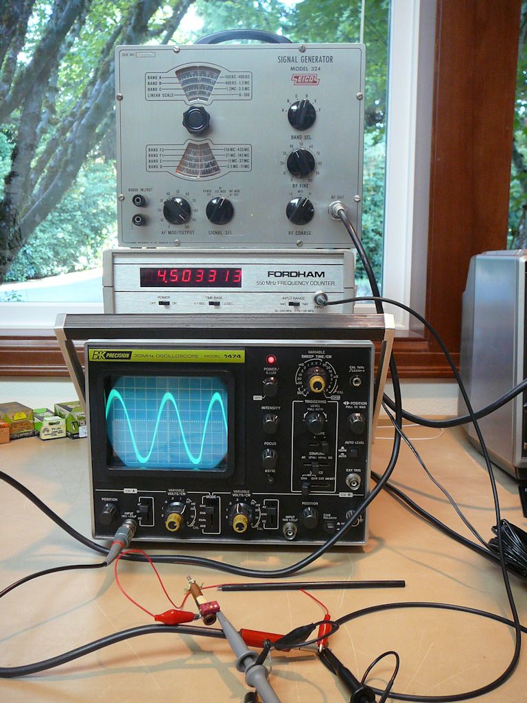 Haven't done much beyond that inspection, except to collect the needed parts. Perhaps I will create a new thread about building the preamp. Phil Nelson Phil's Old Radios http://antiqueradio.org/index.html Last edited by Phil Nelson; 07-28-2015 at 12:15 PM.
|
|
#5
08-08-2015, 01:04 PM
|
||||
|
||||
|
Back to the video preamp plan, with a question about the heater connection. I posted the original article at:
http://antiqueradio.org/art/RCA_Broa...eo_Preamps.pdf The plan I'd like to build is on the last page of the article, which says, "The heater connection is made to pin 4 of the adaptor socket." The heater connection is to service the 12AT7 tube on the preamp. Here's the 12AT7 basing diagram, showing that its heater is center-tapped at pin 9. 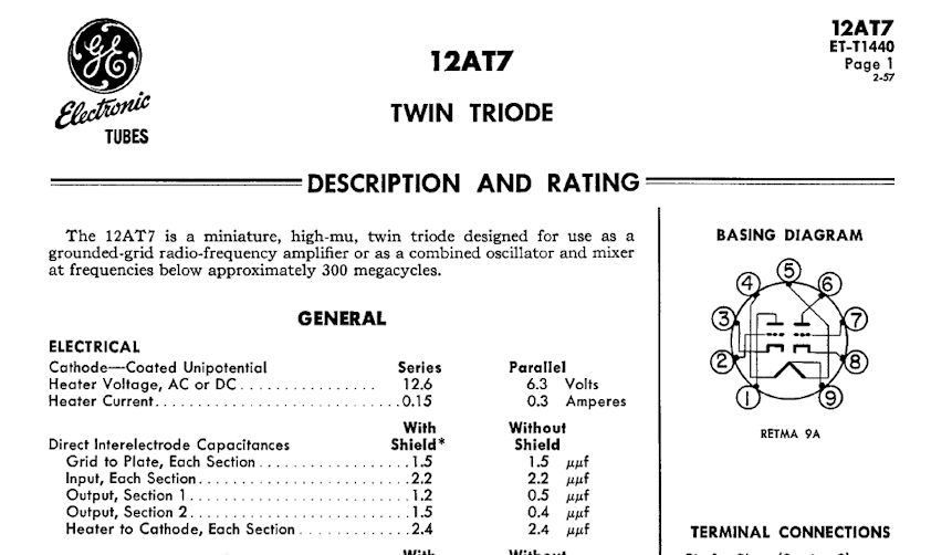 The article tells you to connect the heater connection to pin 4 of the adaptor socket. That's clear, but I want to make sure I understand the way they drew the heater connections in the preamp schematic: 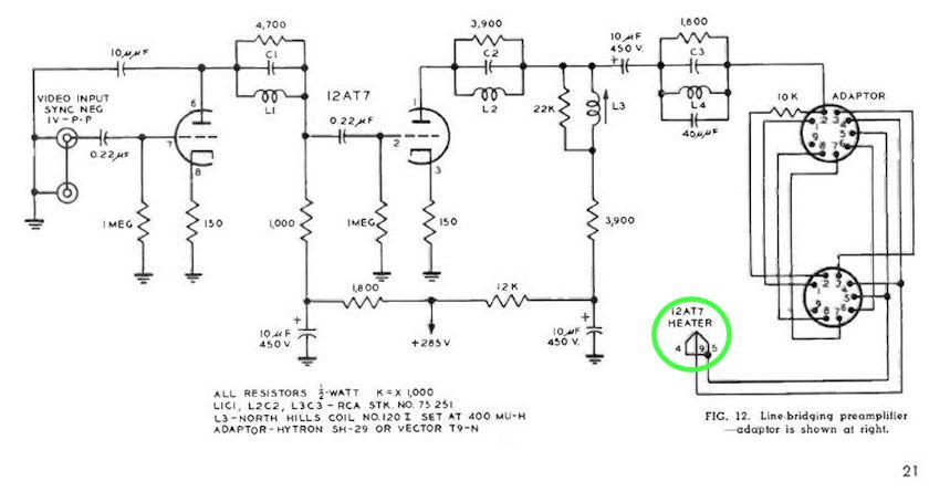 The drawing seems to show pin 4 of the adaptor connecting to pin 9 (the center tap) of the 12AT7. And pin 5 appears to be jumpered to pin 4. Or am I reading the schematic incorrectly? (The ground connection for the heater is made through pin 5 of the 6CL6 1st video amp tube, whose socket the adaptor plugs into.) Phil Nelson
|
| Audiokarma |
|
#6
08-08-2015, 03:33 PM
|
||||
|
||||
|
Quote:
What could be missing on the schematic is the connection from ground of the TV to the ground of the added preamp... IMHO, the wire from pin 5 of the 6CL6 socket should also be connected to ground(s) of the preamp. jr
|
|
#7
08-08-2015, 08:56 PM
|
|||
|
|||
|
Yup, the whole family of 12V twin triodes (12AT7, 'AU7 'AX7, 'AY7, 'AZ7 etc) have the centertap for 6V heater operation.
|
|
#8
02-04-2016, 06:06 PM
|
||||
|
||||
|
OK, after pushing my CTC-4 project aside for a long winter's nap, I hauled it back out.
Last year, I had decided to build a video preamp in hopes of injecting a usable video signal at the 1st video amp, so that I could bypass the set's RF/IF stages and debug my obvious color problem in a "clean" environment. Long story short -- Yes, I did eventually build a video preamp; No, it didn't work as expected (owing to the inevitable leetle wiring mistake by me); and then I got disgusted and worked on other projects. Recently, I got a helpful email from ChrisW6ATV, who asked whether I had ever tried injecting a video signal from my Sencore VA62A, using the Drive Output jacks at the lower right of the front panel. Chris mentioned that you can set the Drive Range level to 3VPP and basically accomplish what I wanted to build a video preamp for (that is, inject a somewhat stronger-than-standard video signal). He reported getting good color on his CTC-4 when injecting video in this manner. Duh! So, here we go. The VA62A makes good color bars, using the 10-bar pattern referenced in the RCA service manual ( http://antiqueradio.org/art/RCA CTC-...ice Manual.pdf ): 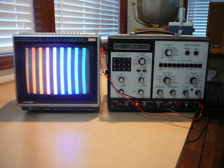 Here is that video signal scoped at the injection point (terminal J on the IF board; the junction of L105/R126/R324 in the RCA schematic): 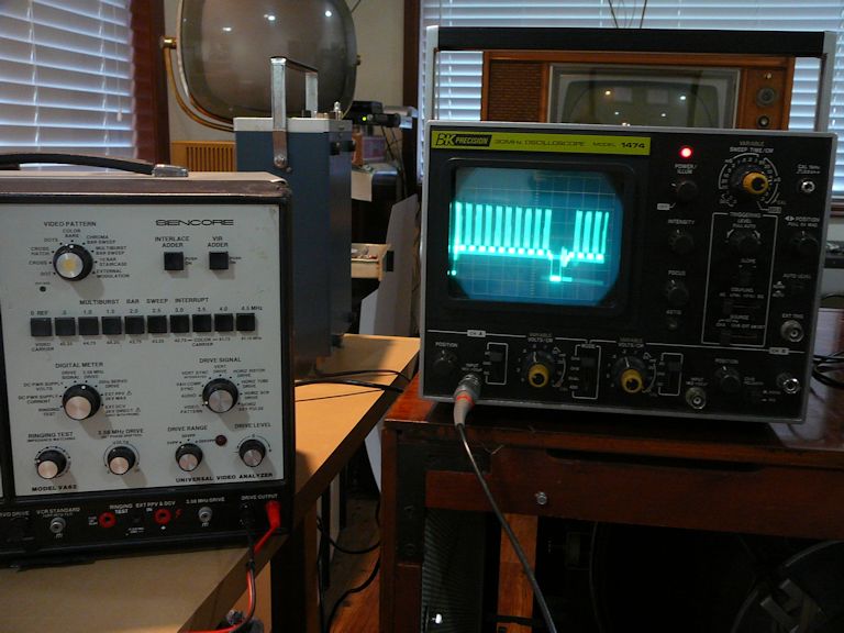 Here's the screen image when that signal is injected (after tweaking L127, reactance coil, to slow down the rolling enough for a photo). Yes, we have seen this barberpole effect many times before: 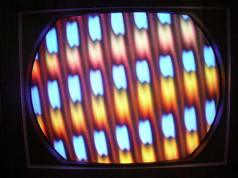 Chris noted that you can pipe an external video source through the VA62 using its video jack in the rear. To try that out, I set a second generator to display NTSC color bars and sent that signal through the VA62: 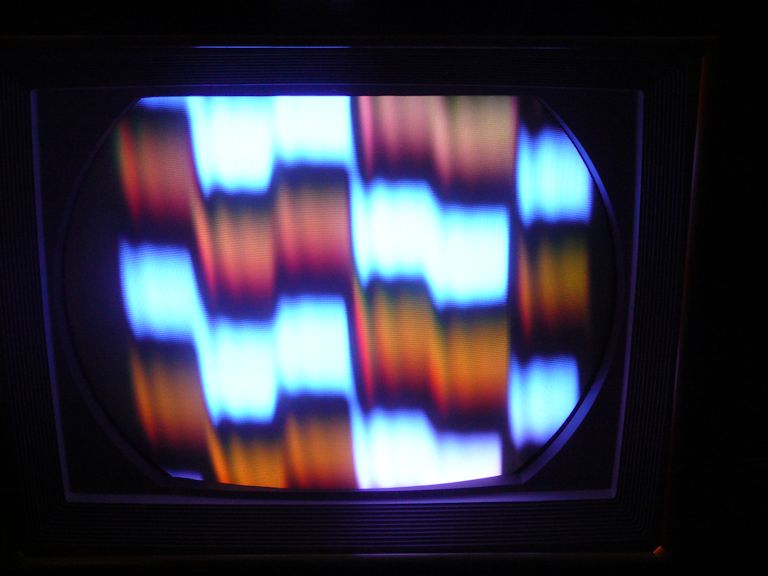 Of course, you can also inject a DVD video signal through the VA62 in that manner, but I'll spare you any more ghastly-looking scenes from the Wizard of Oz. Trust me, they look awful. Now that I can inject a known-good video signal at the right level, I'll back up and: -- Run through color setup procedures as best I can -- Check voltages throughout the color sections -- Scope signals throughout the color sections These things have been done (or sort-of done) before, but now that I can inject a nice strong 10-bar color signal, it should be possible to work through the demodulator phase adjustment procedure on page 49 of the RCA service manual. Other parts of the manual that reference that pattern may also make more sense. As always, I'm open to other ideas. And thanks again to Chris for this bit of advice. Regards, Phil Nelson Phil's Old Radios http://antiqueradio.org/index.html
|
 |
| Thread Tools | |
| Display Modes | |
|
|


 Hybrid Mode
